
Boring Coolants & Cutting Oils for Rough and Fine Boring
Explore boring cutting fluids, rough and fine boring, tool deflection, diameter adjustment, chip evacuation and coolant selection for precision bores with QA Lubricants.
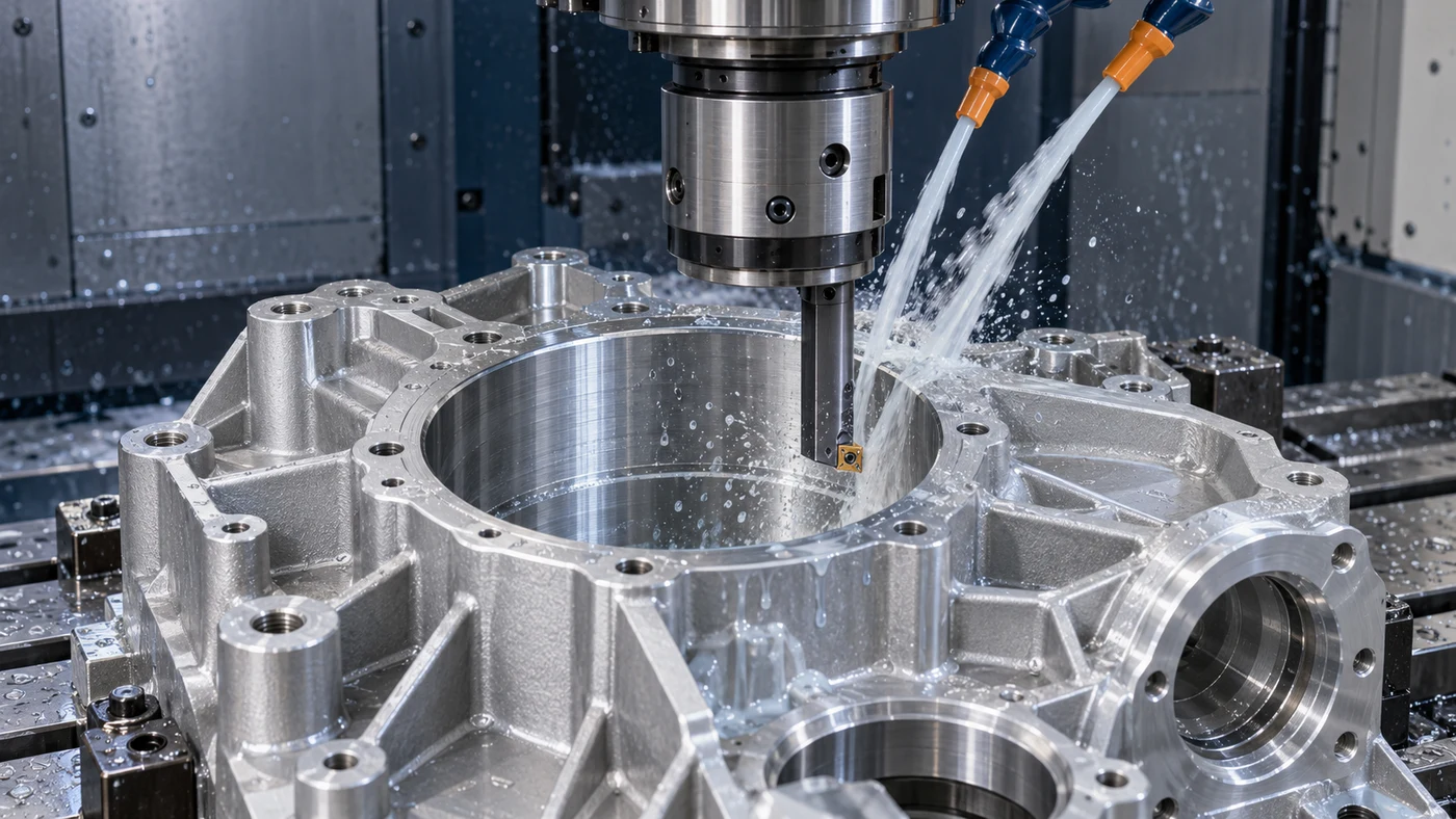
Watch: Boring Coolants & Cutting Oils for Rough and Fine Boring
Define the Boring Operation and the Required Bore
Boring develops an existing hole by removing material with a controlled cutting arrangement. On a machining center, a boring tool rotates; on a lathe, an internal turning bar commonly cuts while the workpiece rotates. Rough boring and fine boring also serve different stages of the process. Begin with the drawing and the existing bore: identify the finished diameter, depth, surface requirement and permitted size and form variation. Include location, concentricity or other geometric requirements where specified. Review interruptions, shoulders and whether the bore is blind or through. A qualified process may correct certain earlier errors when enough stock and the right tooling are available, but every recovery has limits. The cutting fluid supports that complete process. Its selection should be tied to the actual roughing or finishing operation, material, tool assembly and inspection requirement.
Prepare Consistent Stock for the Finishing Cut
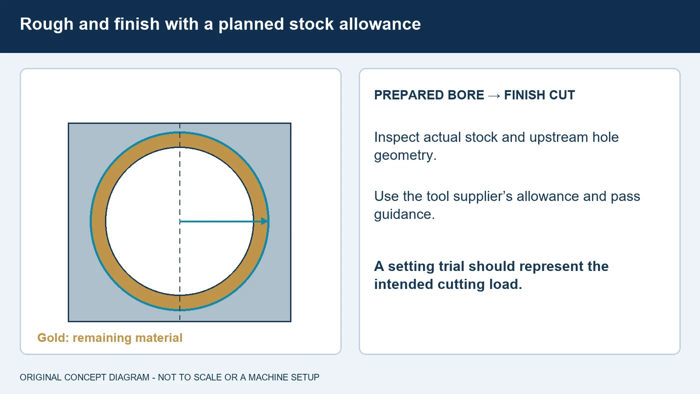
The material left for a boring tool influences cutting forces and the finished result. Inspect the existing hole before deciding how to rough, semi-finish and finish it. Uneven stock, an interrupted wall or a previous position error can make the cutting engagement change around the bore. Use the tool maker's allowance and pass guidance for the actual material and assembly. In fine boring, an unloaded setting does not by itself establish the diameter produced under cutting load. Plan a measured trial that represents the intended finishing conditions, and account for the permitted remaining stock before making a correction. A very light repeat pass can behave differently from the original cut because the engagement and forces have changed. Record the preparation, cutting conditions and measured result so a change in stock allowance is not mistaken for a change in fluid performance.
Understand the Diameter Setting and Tool Geometry
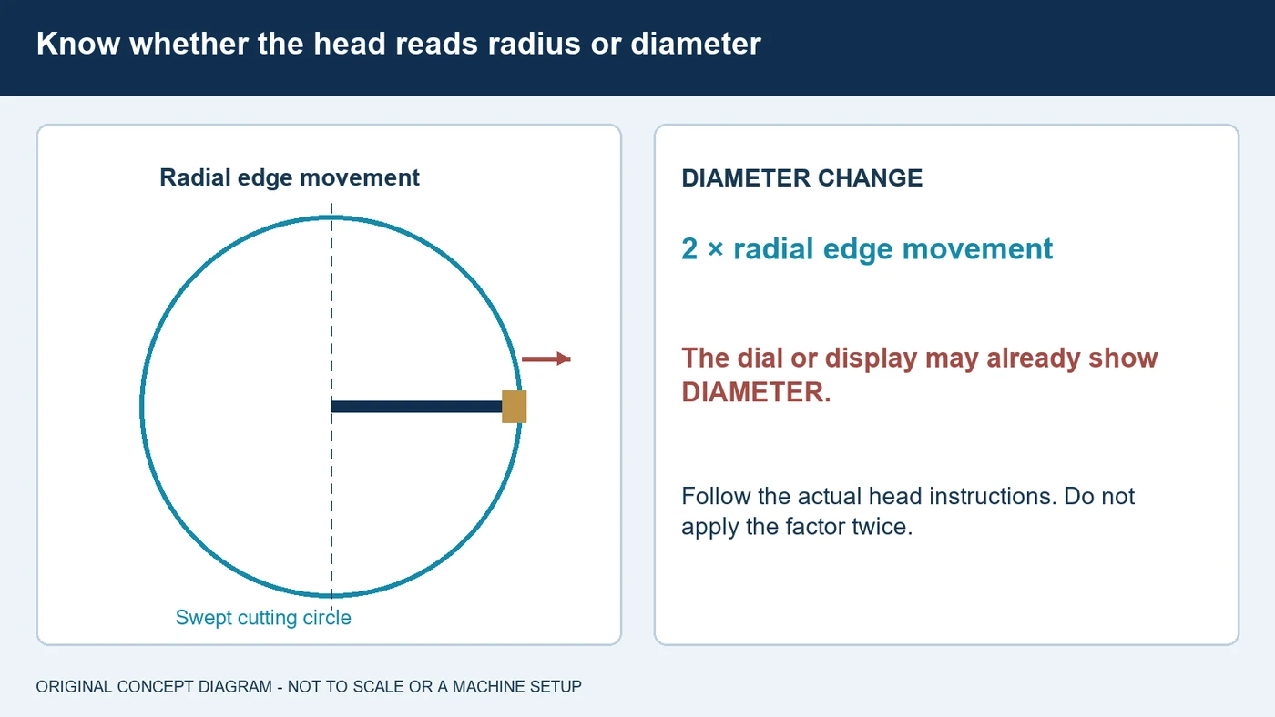
Boring systems have different adjustment mechanisms, cutting-edge arrangements and operating limits. Confirm the meaning of the scale or digital display on the head you are using. A single cutting edge moved radially changes its swept diameter by twice that movement, but the instrument may already show the diameter change. Applying an extra factor of two to a diameter-reading head creates a setting error. Follow the specified setting, locking and measuring procedure for the actual tool. Inspect the mounting interfaces, cutting-edge seat and assembled condition. Choose the insert grade, geometry and nose radius for the material and operation, including the forces and chip behavior the assembly can support. Guide-pad systems and multi-edge tools have their own setting instructions. Coolant cannot compensate for an incorrectly assembled or adjusted tool.
Control Reach, Support and Deflection
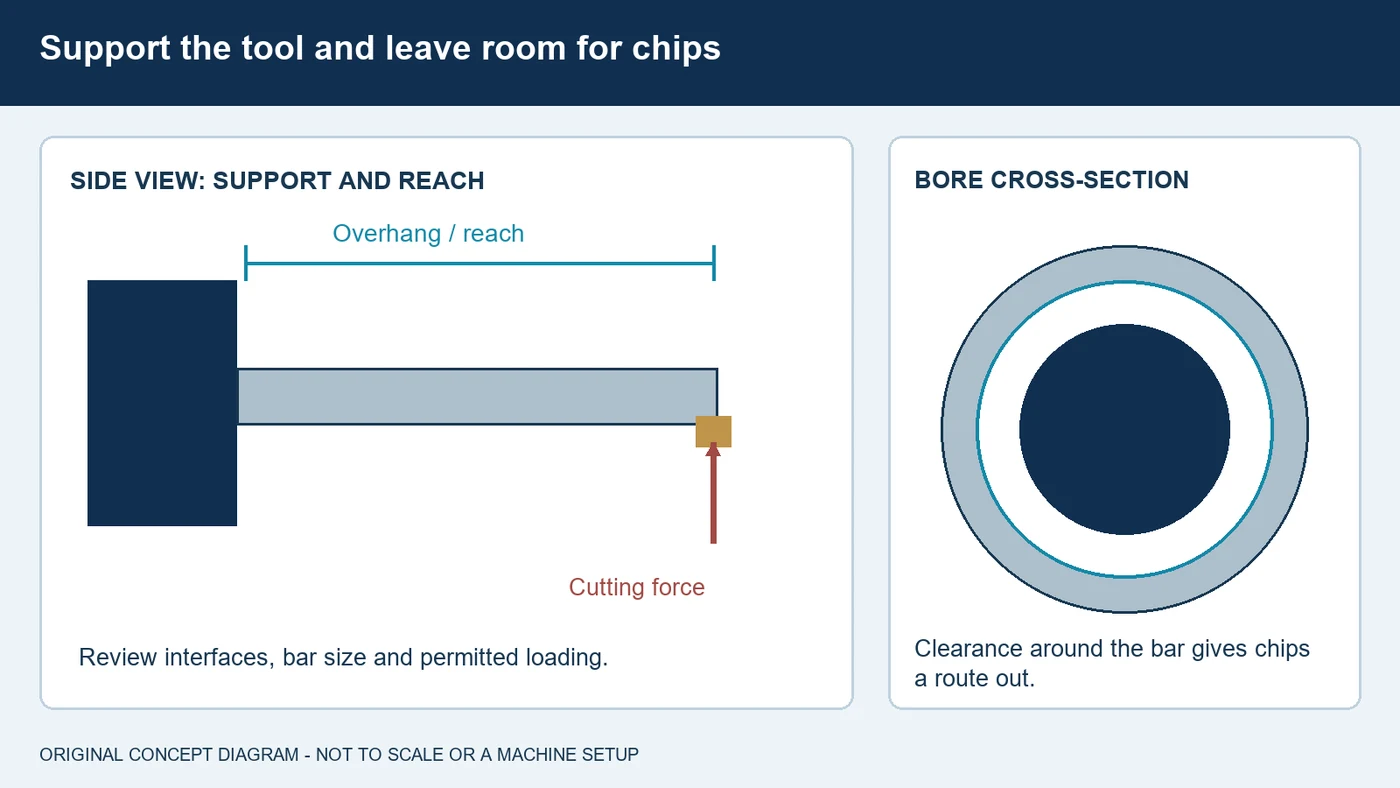
A boring tool works inside a limited space, often with a long reach. Tool overhang, bar diameter, mounting condition and workholding affect its response to the cutting force. Select the supported assembly for the bore, keeping adequate room between the tool and the wall for chip evacuation. Increasing bar size without considering that clearance can introduce a different problem. Review the insert geometry and cutting conditions as part of the stability assessment. Some applications call for a damped tool or an engineered assembly, with specific mounting and load limits. Follow those instructions instead of adopting a universal length-to-diameter rule. Check the spindle interface, holder connections and workpiece support as well. When investigating chatter, record the mechanical setup and the material engagement before concluding that a different oil or coolant is the answer.
Deliver Fluid to the Edge and Give Chips a Route Out
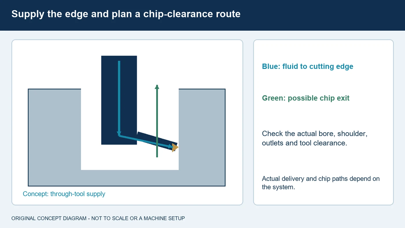
Cutting-fluid delivery in boring is constrained by the tool and the surrounding bore. A large splash near the opening may leave the cutting edge poorly supplied deeper inside the part. Through-tool passages and correctly directed outlets can bring fluid to that region when the assembly is designed for them. Review the actual holder, bar or head, its connections and the machine's supply capability. Chips also need clearance to leave the cut without repeatedly scarring the finished wall or packing around the tool. Blind holes, shoulders and interrupted features add their own access and clearance questions. Confirm the supported flow, pressure and filtration requirements rather than raising pressure without checking the system. Inspect blocked outlets or chip buildup through the approved procedure, with the machine safely stopped before adjustment. A useful fluid trial keeps the delivery arrangement documented and repeatable.
Match the Formulation to the Material and Process
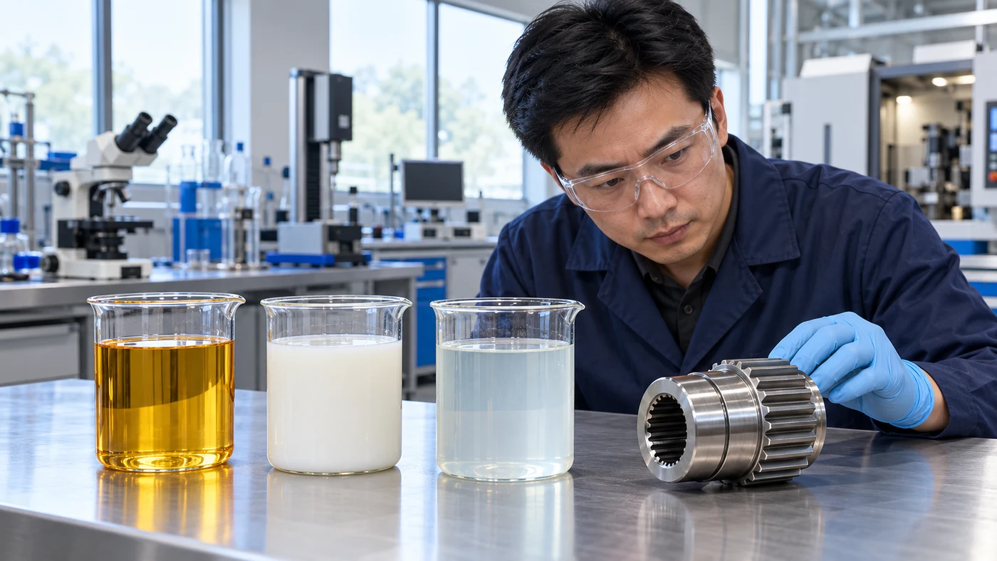
Select a boring coolant or cutting oil around the actual alloy, operation, tool and machine requirements. Water-miscible products and straight oils have different system needs, so compare specific formulations rather than treating every product within a family as equivalent. For aluminum and copper-containing alloys, review staining and additive compatibility, including active-sulfur restrictions where applicable. Stainless steels, titanium and nickel alloys require the grade and condition to be considered alongside the tooling and fluid-delivery strategy. Include the other materials sharing a sump and any residue, cleaning or customer-process limits. Maintain a diluted coolant at its specified application concentration using its product-specific measurement method. Keep a straight oil within its own contamination and condition guidance. Evaluate tool use, accepted bore quality and cleaning results together during a controlled trial.
Separate Size, Roundness, Taper and Surface Problems
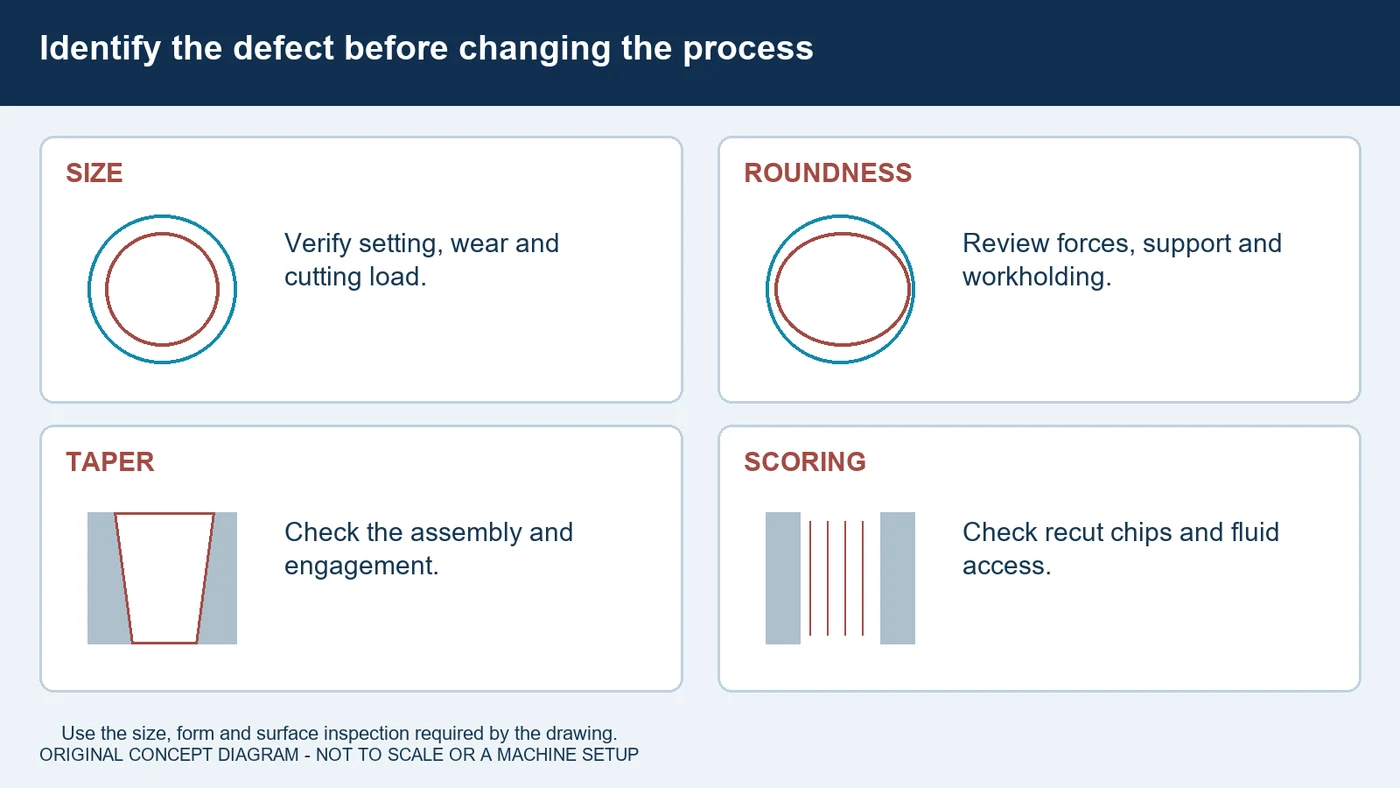
Boring problems become easier to investigate when the defect is clearly described. Inconsistent size calls for checks of stock allowance, adjustment, interfaces and the cutting process. Roundness, taper and chatter need their own review of forces, support, tool condition and workholding. A scored surface may involve chip recutting or poor delivery, while visible feed marks require the insert and cutting conditions to be examined. Confirm the measurement method and part condition before changing the process. A size reading alone may not reveal the form or surface error that matters on the drawing. Use the appropriate tooling supplier's troubleshooting guidance to choose a supported next check, and change variables deliberately. During a fluid trial, record the material, assembly, preparation, delivery and product condition alongside the accepted measurements. More coolant is not a universal remedy for every bore defect.
Bring QA Your Complete Boring Application
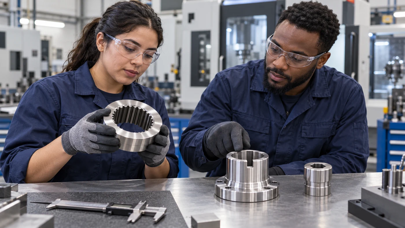
To discuss a boring coolant or cutting oil with QA Lubricants, identify the operation and the part requirements. Tell us whether the job uses a rotating boring head or lathe boring bar, and whether it is roughing, semi-finishing or fine boring. Include the bore diameter, depth, interruptions, required tolerance and surface finish. Share the material's exact grade and condition, the existing-hole measurements and the assembled tooling details. Describe the machine's fluid supply, current product, maintenance practice and the issue you want to solve. Add any staining, cleaning or customer-process restrictions. QA has coolant and cutting-oil options and can help evaluate candidates against the complete application. Agree on inspection and trial criteria before a change. Explore more machining guides at QA Lube dot com, or call one, eight seven seven, eight seven seven, six two two one.
Fluid selection by material
Use these as evaluation questions, not blanket product approvals.
| Material | What to evaluate | What to confirm |
|---|---|---|
| Carbon and alloy steels | Evaluate cutting-edge lubrication, chip control and stable fluid access. | Grade, hardness, insert geometry, roughing/finishing allowance and bore acceptance. |
| Stainless steels | Review adhesion, work hardening, chip shape and delivery inside the bore. | Alloy condition, tool grade, reach, machine-supported supply and cleaning requirements. |
| Aluminum alloys | Evaluate nonstaining lubrication and material buildup at the edge. | Exact alloy, tool coating or cutting material, surface requirement and additive compatibility. |
| Copper, brass and bronze | Check nonstaining chemistry, including active-sulfur compatibility. | Alloy, discoloration limits, other metals sharing the sump and downstream processing. |
| Titanium and nickel alloys | Review formulation, heat control and chip evacuation with the tooling supplier. | Exact material condition, permitted tool application, delivery and process restrictions. |
| Cast iron and hardened materials | Use the cutting strategy supported by the insert and boring system. | Hardness, interruptions, chip or dust handling and the permitted wet/dry method. |
Questions about boring fluids
How does boring differ from drilling or reaming?
Boring enlarges or finishes an existing hole using the selected cutting tool and controlled path. Drilling creates a hole, while conventional reaming finishes a prepared bore with a different cutting arrangement. The appropriate sequence depends on the drawing and process.
Can fine boring correct an off-location hole?
A qualified boring process can address certain position or form deviations only when stock, tooling, alignment and the process permit it. Check the actual geometry and remaining material; do not assume that any finish pass can recover every upstream error.
Does a boring-head dial show radial or diameter change?
It depends on the head. Moving one cutting edge radially changes its swept diameter by twice that movement, but a dial or display may already report diameter. Follow the exact head’s instructions to avoid doubling a correction twice.
Will more coolant stop boring chatter?
Chatter also depends on support, reach, bar diameter, insert geometry, cutting conditions and workholding. Review the mechanical setup and fluid delivery together using the tool supplier’s guidance.
Which fluid is best for boring aluminum or stainless steel?
Match the actual formulation to the alloy, tool, operation and machine. Evaluate compatibility, lubrication, chip handling, finish and cleaning in a controlled trial rather than selecting solely from a fluid family name.
What information does QA need for a boring-fluid inquiry?
Share the material, bore diameter and depth, required tolerance and finish, existing-hole condition, tooling assembly, fluid delivery, current product and the problem you want to solve. QA has coolant and cutting-oil options.
Discuss your application with QA
QA Lubricants has coolant and oil options. Send us the operation, alloy, hardness, tooling, current fluid and the problem you want to solve.
Discuss My ApplicationShop Water Diluted CoolantsShop Straight Cutting OilsTechnical references
- Sandvik Coromant: rough and fine boring application guide
- Sandvik Coromant: internal turning, bar support and fluid delivery
- BIG DAISHOWA: fine boring troubleshooting
- BIG DAISHOWA: size consistency, allowance and finish in fine boring
- BIG DAISHOWA: common boring problems and coolant access
- MAPAL: fine boring of interrupted bores with multiple cutting edges
- MAPAL: staged fine-boring application and guide-pad tooling
- Blaser Swisslube: product-specific coolant concentration measurement
Original educational content and illustrations. Confirm current machine, tool and fluid instructions. Trademarks belong to their respective owners.