
Gear Grinding Oils and Coolants
Explore grinding oils and coolant selection for generating and profile gear grinding, with guidance on tooth-flank delivery, dressing, filtration and inspection.
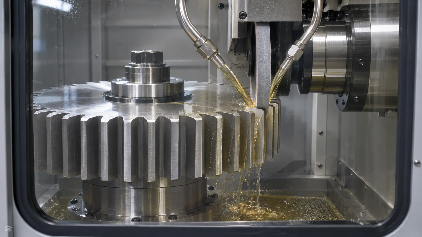
Watch: Gear Grinding Oils and Coolants
Gear Grinding: Precision Tooth-Flank Finishing
Gear grinding finishes tooth surfaces using an abrasive tool and controlled machine motion. It is often used after heat treatment, when the required tooth geometry and surface condition must be achieved on hardened gears. Gear grinding oil must support that process while carrying away heat and grinding debris. The best starting point is the actual tooth system, material, hardness, stock distribution and drawing. A spur gear, helical gear, internal ring and bevel gear do not present the same access or contact conditions. This guide concentrates on cylindrical gear grinding, with a reminder that bevel grinding requires its own equipment review. QA has coolant and oil options for evaluation. Define the permitted fluid, abrasive system, delivery arrangement and acceptance checks together before comparing formulations.
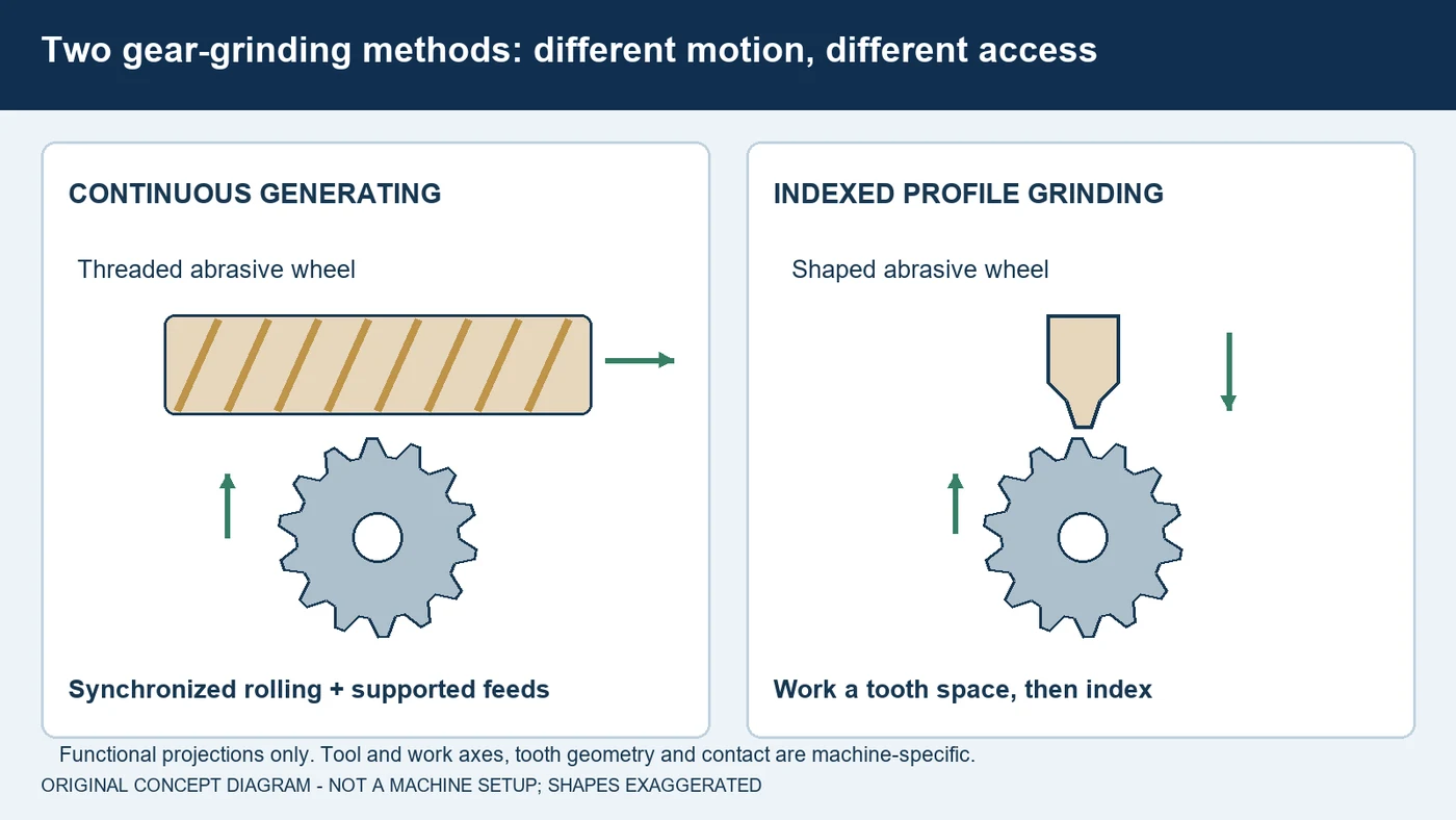
Generating and Profile Grinding Use Different Motions
Continuous generating gear grinding uses a threaded abrasive wheel and synchronized rotation with the gear. The tooth form results from the generating motion rather than simply copying the entire gap from a single disk. A traverse and a controlled wheel-shifting strategy are part of supported systems. Profile gear grinding instead uses a wheel shaped for the required flank or tooth-space geometry and indexes between tooth spaces. It can be useful where geometry or interfering features limit access for a generating tool. Neither process is a universal substitute for the other. Internal and external gears also require different access arrangements. Identify the supported machine cycle, wheel, tooth geometry and modifications. Do not transfer an oil delivery layout, dressing program or grinding setting from a different process simply because both parts are gears.
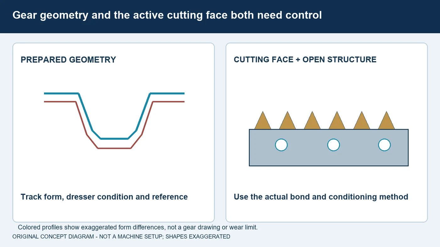
Keep Tooth Geometry and Wheel Condition Under Control
Gear grinding combines a geometry requirement with a cutting-condition requirement. Abrasive grains remove material; the bond holds them, and the wheel structure provides space for fluid and debris. A dull or loaded working face can change the interaction even before a gross form error is obvious. With a dressable wheel, the dresser and its reference affect the prepared geometry as well as cutting condition. Other wheel constructions have different preparation and replacement rules. Conventional abrasives and CBN systems should not be treated as interchangeable based on outside dimensions alone. Record the wheel specification, preparation history, dresser condition and supported compensation. Check tooth-flank results across the interval. During a fluid comparison, keep the wheel and conditioning state comparable so a changed tool is not mistaken for a changed formulation.
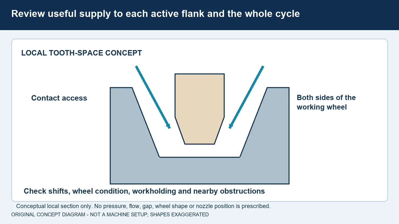
Deliver Fluid to the Active Tooth-Flank Contact
A wet gear is not proof that sufficient fluid reaches the active grinding contact. Review the nozzle arrangement for the actual wheel, tooth width and machine motion. Profile grinding can require access beside a relatively narrow wheel, while a generating process has its own changing contact and wheel-shift conditions. Include the effects of wheel preparation, changed diameter, workholding and nearby shoulders. The delivery system must remain compatible with the enclosure and supported machine travel. Some suppliers offer purpose-designed side jets and manifolds for gear grinding; these are application-specific components, not a universal nozzle prescription. Confirm delivered flow and pressure with the equipment and nozzle suppliers. Check fluid return and debris removal as well. More splash or a larger pump does not establish that the grinding interface is being supplied correctly.
Match Grinding Oil to the Machining Process
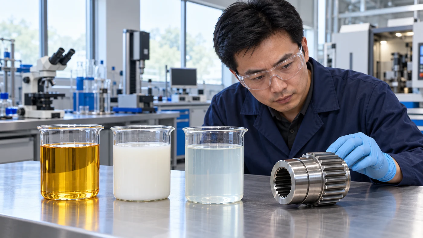
Gear grinding oil is a metalworking process fluid, and the word gear does not make a gearbox lubricant suitable. Dedicated grinding oils are commonly used in gear hard finishing, but the actual machine instructions determine the permitted fluid type. Evaluate viscosity at the relevant operating conditions, lubrication, filtration behavior, air release, foam control, corrosion protection and residues. Confirm compatibility with the material, wheel bond, seals and downstream cleaning. Do not assume that a stronger additive package or a higher viscosity is automatically better. The fluid also has to work with the specified extraction and fire-protection arrangement; a flash-point value alone is not an operating permission. If a particular system permits diluted coolant, use that product's mixing, concentration and water-quality instructions. QA has coolant and grinding-oil options for evaluation against the complete application.
Manage Cleanliness and Temperature as Process Conditions
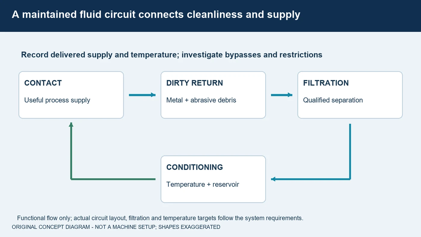
Gear grinding produces fine metal and abrasive debris. Select filtration for the actual fluid, contaminants and process, and maintain the return path so dirty fluid does not bypass the intended treatment. A filter label alone does not prove clean fluid is reaching the contact. Record the delivered supply and investigate restrictions when filters load or fluid condition changes. Temperature is another process variable. Control it using the machine and fluid-system requirements, and distinguish startup conditions from stabilized production. A changed oil temperature can affect viscosity and the delivery system while machine and part temperature affect the measurement context. Keep those conditions consistent during trials. For a shared circuit, account for all machines, alloys and abrasive bonds. Compare formulations using maintained fluid and recorded system conditions rather than an uncontrolled sump change.
Inspect Geometry, Texture and Thermal Condition Separately
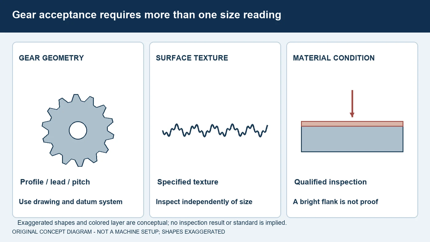
A correct tooth thickness alone does not establish that a finished gear is acceptable. Use the specified gear inspection plan to evaluate profile, lead, pitch, runout and required modifications against the drawing and datum system. Surface texture and relevant functional checks add different information. Keep the part support, cleanliness and measurement temperature consistent. Thermal condition is a separate question: a smooth or bright flank is not proof that grinding damage is absent. Use the material-appropriate inspection procedure required for the component. If results drift after dressing or as production warms up, examine the tool, workholding, stock distribution, delivery and system condition before assigning a cause. On-machine checks and process signals are useful evidence, but the acceptance plan determines what must be measured or verified before the process is approved.
Plan a Gear-Grinding Fluid Trial Around Accepted Parts
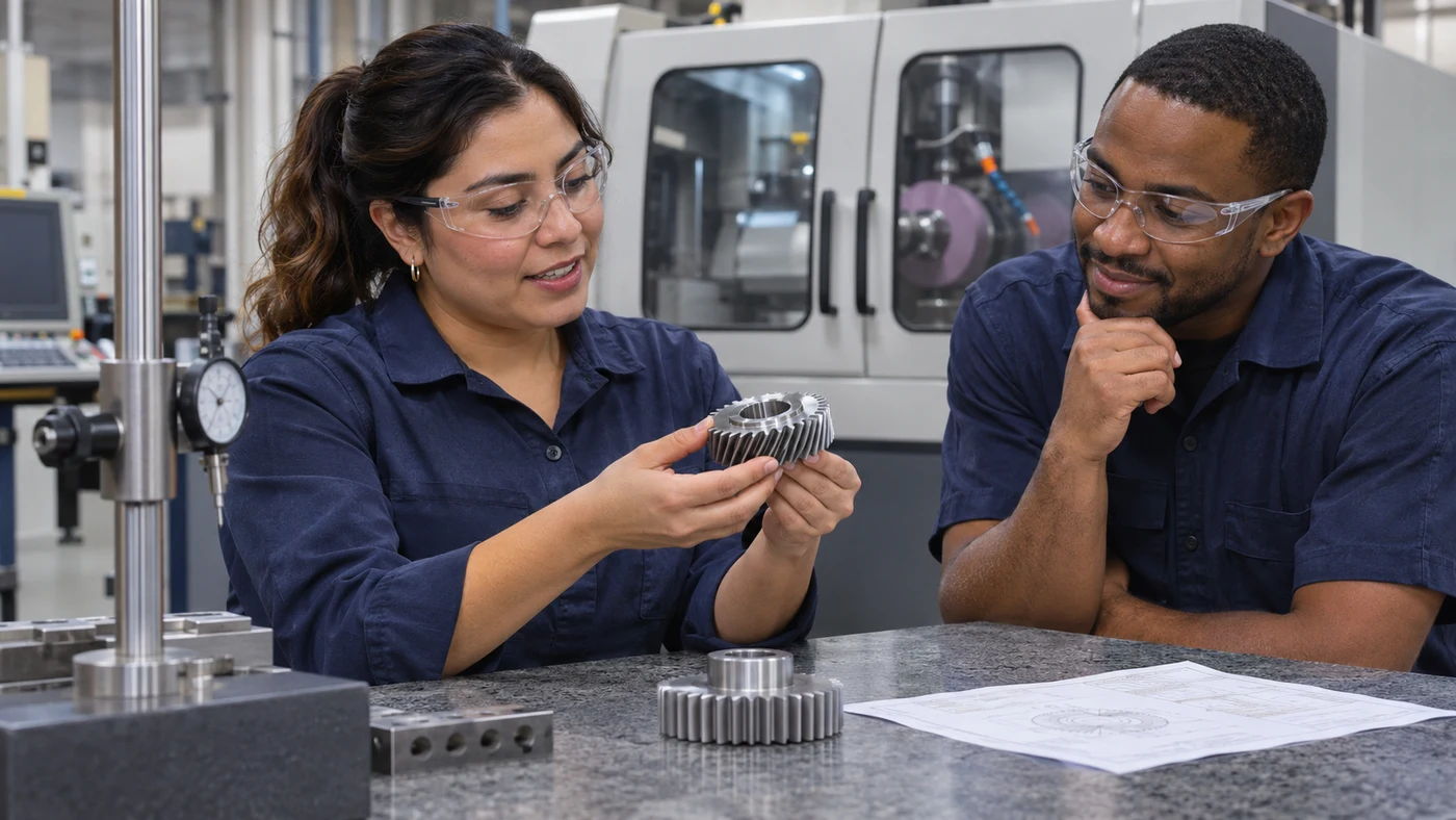
For a gear-grinding inquiry, send QA the gear drawing, alloy and heat-treatment condition, incoming stock distribution and finished-part requirements. Identify whether the process is generating, profile or bevel grinding, and whether the gear is external or internal. Include the wheel and bond, dresser, preparation interval, workholding and supported cycle. Provide the current fluid specification, supply arrangement, filtration, temperature and fluid-maintenance records. Describe the concern with inspection data, and note its relationship to dressing, startup or a particular tooth region. QA has coolant and oil options. Agree on a controlled trial and compare accepted gears, wheel condition, preparation requirements and fluid maintenance together. Confirm the final formulation and operating instructions with the equipment, abrasive and fluid suppliers. There is no universal grinding-oil grade or machine setting for every gear.
Fluid selection by material
Use these as evaluation questions, not blanket product approvals.
| Material | What to evaluate | What to confirm |
|---|---|---|
| Case-hardened alloy steel gears | Evaluate the actual case condition, remaining grinding stock and thermal demand. | Permitted grinding oil, wheel system, tooth geometry and qualified surface-integrity checks. |
| Through-hardened steels and tool steels | Match lubrication, abrasive condition and stock removal to the actual hardness and component. | Abrasive and bond, conditioning, contact delivery and dimensional acceptance. |
| Stainless steels and nickel alloys | Confirm process suitability, alloy-specific lubrication and loading behavior. | Actual wheel system, formulation compatibility, heat control and downstream cleaning. |
| Bronze, aluminum and other nonferrous gears | First confirm that grinding is the qualified finishing route; check staining and material loading. | Alloy-specific additive compatibility, abrasive choice and residue requirements. |
| Mixed-material or shared systems | Review all alloys, wheel bonds and machines using the fluid circuit. | Cross-contamination, filtration, permitted fluid types and maintenance practices. |
Questions about gear grinding fluids
What is the difference between generating and profile gear grinding?
Generating grinding uses a threaded abrasive tool and synchronized rolling motion. Profile grinding uses a shaped wheel and indexes between tooth spaces. The supported machine, tooth geometry and clearance determine suitability.
Can gearbox oil be used for gear grinding?
Do not substitute it on the basis of the word gear. Grinding is a metalworking process with specific fluid, delivery, filtration and machine requirements. Use a formulation permitted for the actual grinding system.
Is straight grinding oil always required?
Grinding oil is common in gear hard finishing, but the machine and process determine the permitted fluid. Do not convert a system to oil or diluted coolant without the equipment and fluid suppliers confirming suitability.
Does visible coolant splash prove the gear flank is supplied?
No. Verify useful supply at the active contact throughout the actual cycle, including shifts, wheel preparation and nearby obstructions. Use the supported nozzle and pump arrangement.
Does a good tooth-thickness reading rule out grinding damage?
No. Tooth thickness, profile, lead, pitch, surface texture and material condition are distinct acceptance questions. Follow the drawing and qualified inspection procedure.
Which QA oil should be selected for gear grinding?
QA has coolant and grinding-oil options. Provide the alloy, gear geometry, machine process, wheel, dressing, delivery and acceptance requirements so the actual formulation can be evaluated.
Discuss your application with QA
QA Lubricants has coolant and oil options. Send us the operation, alloy, hardness, tooling, current fluid and the problem you want to solve.
Discuss My ApplicationShop Water Diluted CoolantsShop Straight Cutting OilsTechnical references
- Reishauer: continuous generating gear grinding
- Reishauer: profile grinding and interfering contours
- Gleason: profile grinding for external and internal gears
- Norton: abrasive selection for worm, profile and bevel gear grinding
- Reishauer: threaded wheel grains, bond and pores
- Norton: CBN and conventional gear grinding wheel constructions
- Cool-Grind: purpose-designed gear grinding delivery arrangements
- FUCHS: machining and special grinding oil selection
- UNITED GRINDING: filtration and thermal regulation
- Reishauer: gear grinder oil flow and thermal design
- Gleason: profile, lead and pitch inspection
- UNITED GRINDING: thermal damage and appropriate verification
- Norton: truing, dressing and working-face condition
- Blaser Swisslube: measuring diluted coolant concentration
Original educational content and illustrations. Confirm current machine, tool and fluid instructions. Trademarks belong to their respective owners.