
Gear Shaping Cutting Oils & Coolants for Internal and External Gears
Gear-shaping cutting oil and coolant selection: internal and external gears, reciprocating cutters, return relief, chip removal, material compatibility and gear-quality checks.
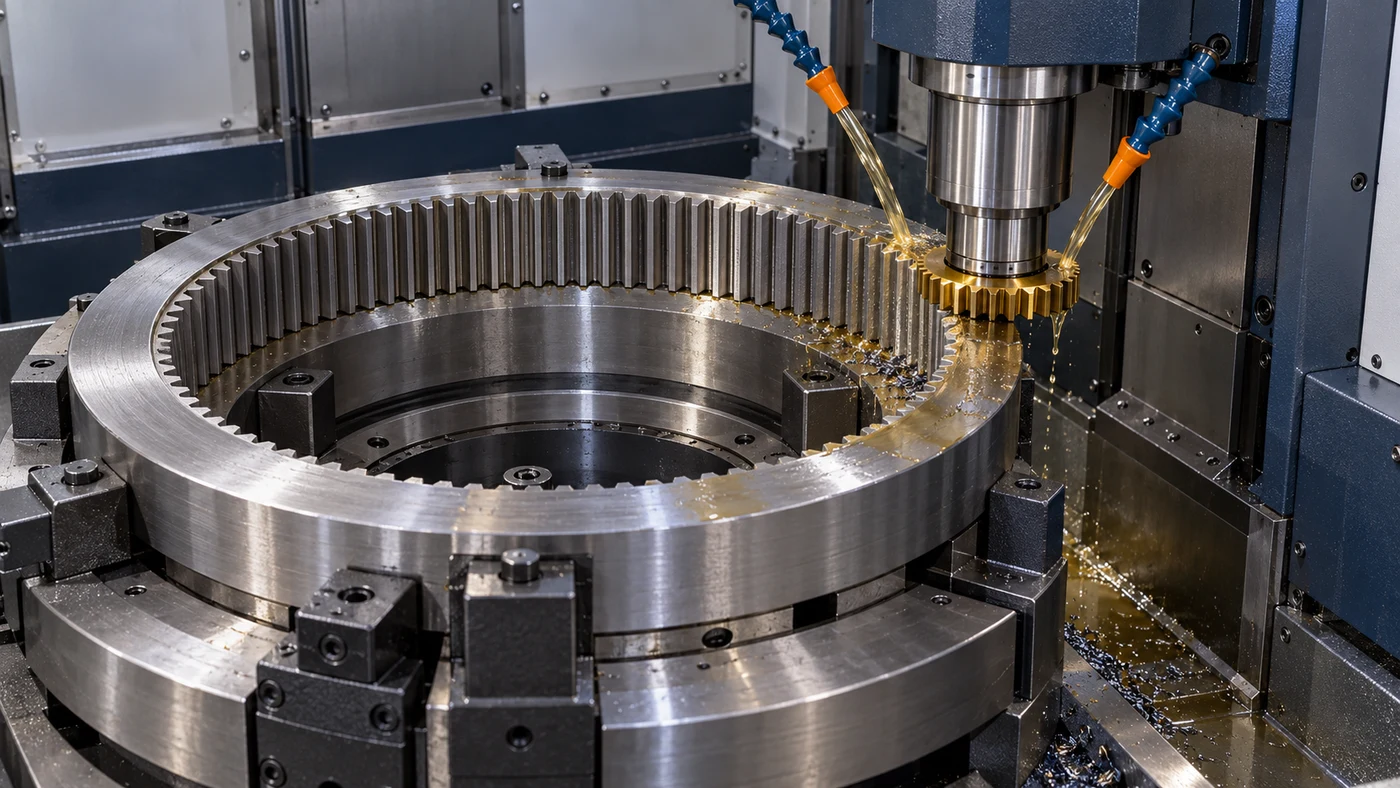
Watch: Gear Shaping Cutting Oils & Coolants for Internal and External Gears
Understand the Reciprocating Generating Process
Gear shaping uses a pinion-shaped cutting tool and coordinated generating motion to produce gear teeth. The cutter reciprocates through the cutting region while its rotation is timed with the workpiece. This process can produce internal or external gears with suitable tooling and machine arrangements. It is different from the rotating hob used in gear hobbing, the continuously rotating crossed-axis arrangement used in power skiving, or an ordinary single-point shaping operation. Start with the gear drawing and its manufacturing stage. Record tooth count, module or diametral pitch, pressure angle, face width, helix and any required modifications. Establish whether the shaped surface is a finished feature or preparation for later finishing. Those requirements define the application that the machine, cutter and fluid must support. QA has coolant and cutting-oil options, but fluid selection follows the complete process rather than a universal gear-shaping recipe.
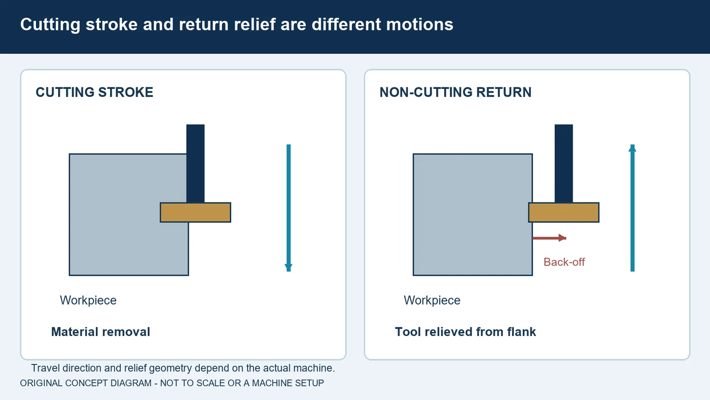
Plan Stroke, Return Relief and Clearance
The cutting stroke and the return stroke have different jobs. Material is removed during the intended cutting motion; the return arrangement must avoid unwanted rubbing or interference. Machines provide specified relief or back-off motions, and their timing must suit the cutter and workpiece. Do not assume every shaper uses the same stroke direction, relief amount or clearance. Review the entire travel envelope, including approach, overrun and any nearby shoulder or bottom feature. Internal gears require particular attention to the space available for the cutter, chips and supporting assembly. A feature described as near a shoulder or inside a blind recess still needs a proven clearance arrangement. Fluid cannot create missing mechanical space. Use the equipment and tooling procedures to establish stroke position and return behavior, then confirm the setup before evaluating finish or tool life. Keep these settings documented so a later fluid trial compares the same mechanical process.
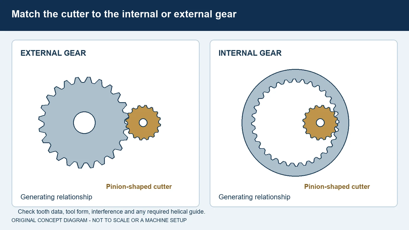
Match Cutter Form and Gear Geometry
Gear shaper cutters are supplied in forms such as disc, counterbore and shank types. The appropriate form depends on gear geometry, access, machine interface and the workholding arrangement. A cutter that fits inside a ring is not automatically suitable for generating its teeth. Tool selection must also address the tooth system, cutter diameter, tooth-count relationship and possible interference. Review the required profile and finishing allowance with the tooling supplier. Helical gear shaping adds another requirement: the cutter needs the specified helical relationship during the reciprocating stroke. Machines may produce that relationship through a mechanical guide or an electronic guide, with tooling matched to the application. A straight reciprocating motion alone is not a general solution for every helix. Before discussing an oil or coolant change, identify the complete cutter specification, substrate and coating, plus the supported cutting method. Record those details with the gear drawing and machine model.
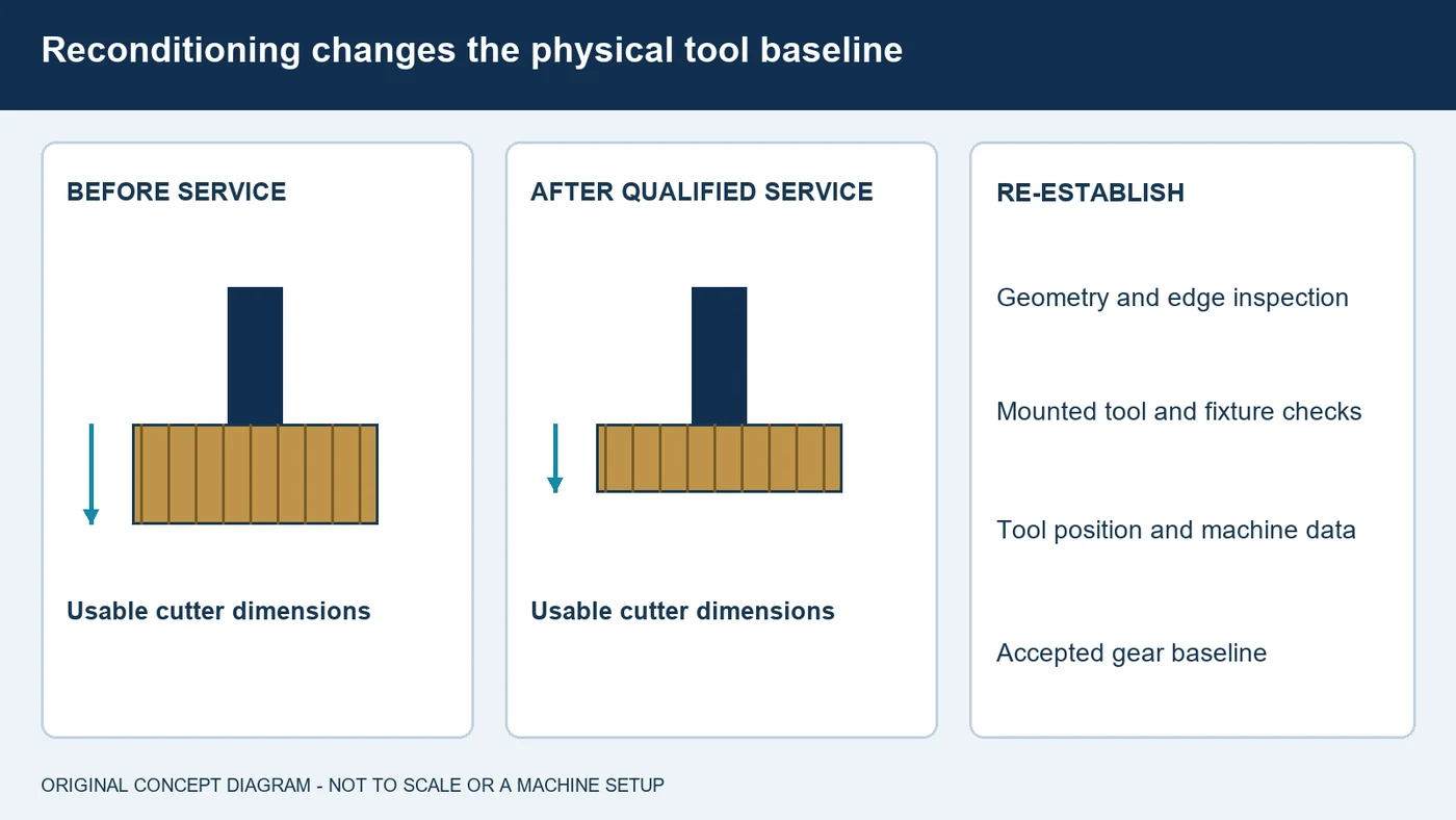
Control Mounting and Reconditioning
A stable setup begins with the cutter assembly, the gear blank and their supports. Check the mounted tool, fixture seating and workpiece rigidity using the machine's procedures. A fluid comparison becomes difficult to interpret if cutter runout or clamping changes between trials. Shaper cutters also have a reconditioning history. Sharpening, deburring and any coating work must preserve the tool geometry required for the application. Have the tool inspected after service and track its remaining usable dimensions. Reconditioning can change dimensions used by the setup, so confirm tool position and the applicable machine data before restarting production. Do not treat the re-sharpened cutter as identical to its earlier physical state without those checks. Establish an accepted baseline with the actual tool, blank and fixture. Then evaluate a formulation or delivery change while holding the relevant mechanical conditions consistent. Record the parts inspected and the cutter condition alongside the fluid information.
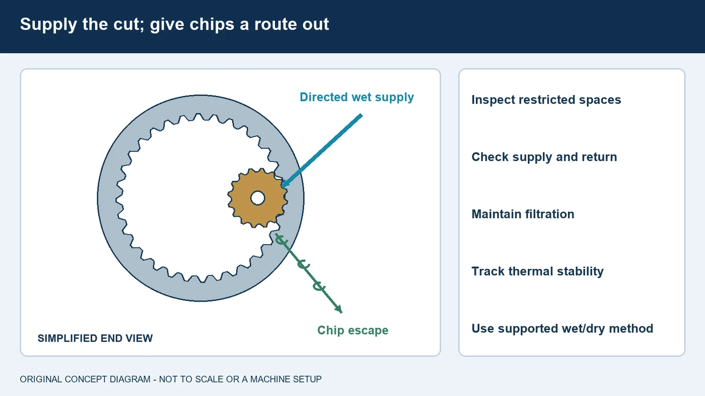
Supply the Cut and Remove Chips
Gear shaping is available in wet and dry configurations, but the choice belongs to the qualified machine and tool system. A dry process is not established by simply turning off a wet machine's pump. For wet shaping, observe the fluid reaching the cutting region during the actual cycle. Check nozzle access, supply stability, screens, filtration and the return path. An internal ring or nearby shoulder can leave limited room for chips to escape, so inspect where chips collect rather than judging delivery by the amount visible in the enclosure. Keep chip handling within the equipment's intended arrangement. Temperature behavior also deserves attention. Fluid circulation and contact with machine structures can influence thermal stability; a colder supply is not automatically the correct remedy for dimensional drift. Record the machine's warm-up state and the relevant fluid temperatures over the run. Evaluate accepted gear quality together with chip removal, tool condition and cycle consistency.
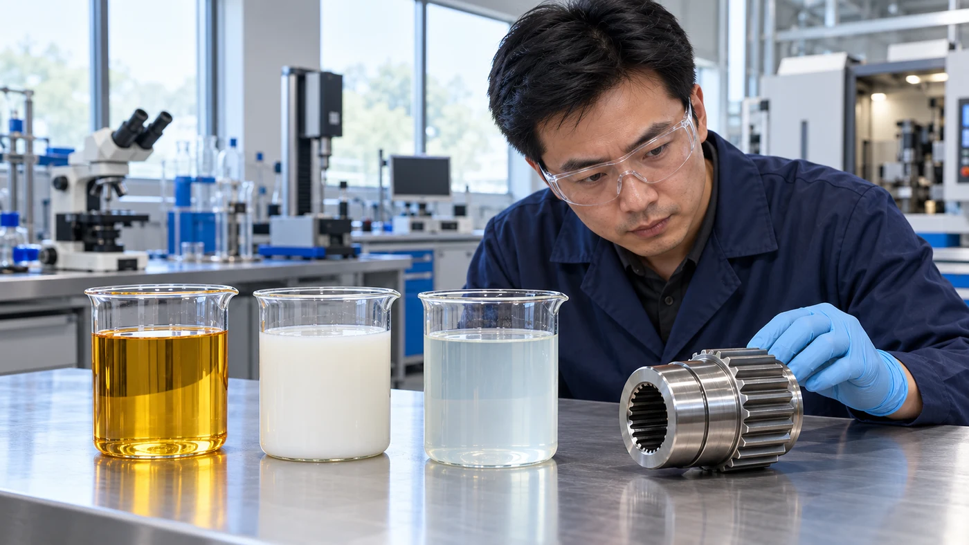
Match Formulation to Material and Downstream Work
The material description should include the actual alloy, hardness and heat-treatment condition. Carbon steel, stainless steel, aluminum and copper alloys do not present identical lubrication, staining or cleaning requirements. In a supported wet process, compare the specific cutting oil or water-miscible formulation with the machine and tooling requirements. Consider lubrication, viscosity, delivery, corrosion protection and compatibility with seals and other contacted materials. Do not assume every extreme-pressure additive is suitable for every nonferrous alloy. Some cutting oils carry explicit copper-alloy discoloration cautions, which is a reason to confirm the chosen product rather than generalize from its category. Include the operations that follow shaping: cleaning, storage, heat treatment and final finishing may affect the decision. If a water-miscible product is qualified, measure and maintain its concentration using that product's instructions and refractometer factor. There is no single concentration, viscosity or additive package that this guide assigns to every gear-shaping application.
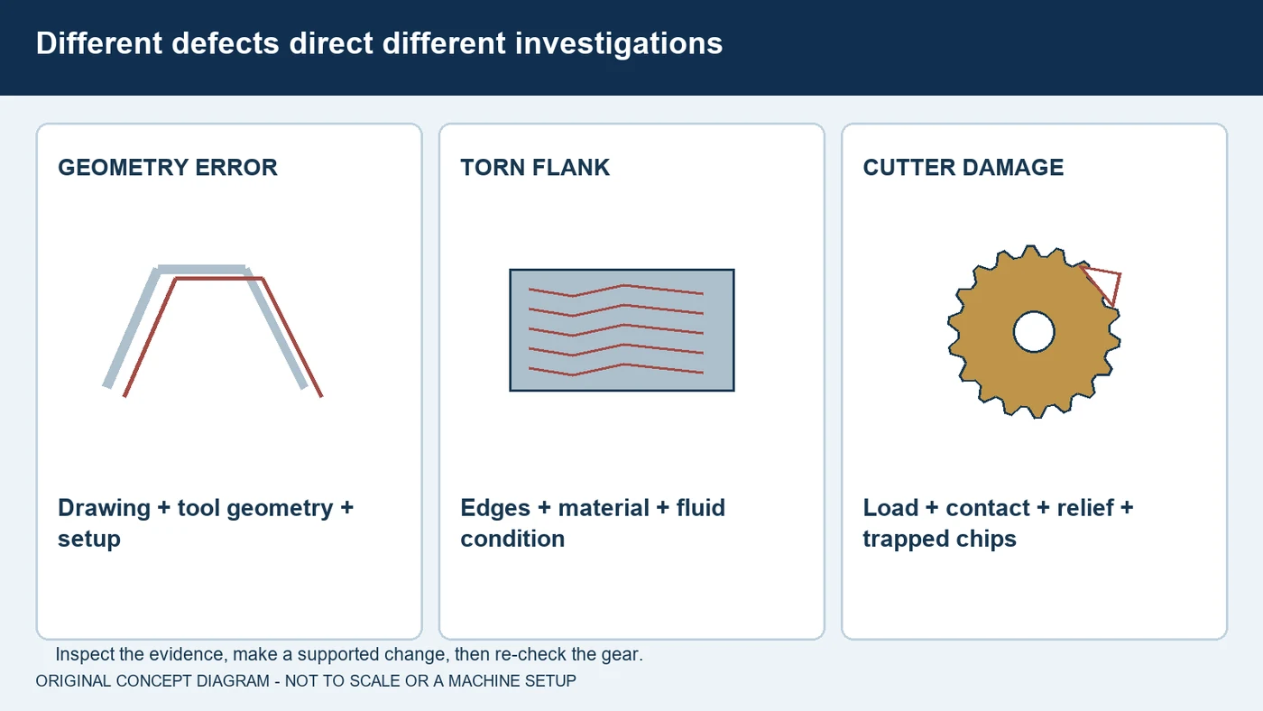
Separate Geometry Errors, Tearing and Cutter Damage
Inspect the gear characteristics required by the drawing and the manufacturing stage. These can include tooth profile, pitch, helix or lead, tooth thickness and runout. Use the applicable inspection method and acceptance requirements rather than a generic quality label. A profile or lead error, a torn flank and a chipped cutter do not necessarily share the same cause. Geometry problems call for a review of tool geometry, mounting, machine condition and the generating setup. Surface tearing also warrants examination of cutting edges, material behavior and fluid condition. Unexpected cutter damage calls for checks of load, shoulder contact, return relief and chips packed into restricted spaces. Stop and investigate an interference condition rather than trying to flush through it. Make a supported change, inspect the resulting gear and preserve the trial record. Accepted tooth quality and repeatable cutter behavior are better evidence than a temporary improvement in surface appearance alone.
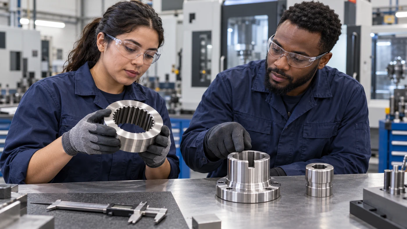
Bring QA the Complete Gear-Shaping Application
For a gear-shaping fluid review, send QA the gear drawing or relevant tooth data, material grade and hardness, internal or external geometry, face width and nearby features. Include the machine model, cutter form, substrate, coating and reconditioning status. Describe whether the process is qualified for wet or dry operation, and provide the current product, delivery arrangement and any concentration information. Explain the result you want to improve: for example, flank tearing, chip removal, cleaning, corrosion control or consistency through a production run. Photographs and inspection records help separate a fluid question from a tooling or clearance problem. QA has coolant and cutting-oil options and can work with you on an application-specific evaluation. Agree on the conditions, parts to inspect and measures of success before the trial. Keep the machine and tool makers involved where their requirements govern the process, and confirm the result on your actual gear.
Fluid selection by material
Use these as evaluation questions, not blanket product approvals.
| Material | What to evaluate | What to confirm |
|---|---|---|
| Carbon and alloy steels | Review lubrication and load for the actual hardness and condition. | Steel grade, heat treatment, cutter coating, finish and later heat treatment. |
| Stainless steels | Assess the qualified tool and formulation for the specific alloy and cutting load. | Alloy, rigidity, edge condition, chip behavior and permitted chemistry. |
| Aluminum alloys | Confirm non-staining compatibility, lubrication and chip removal. | Alloy, finish, cleaning requirements and machine approval of the fluid. |
| Copper and brass alloys | Confirm staining compatibility; do not assume all EP chemistry is suitable. | Exact alloy, product compatibility statement, discoloration and wash trials. |
| Cast iron | Review particulate handling and the machine-supported wet or dry arrangement. | Iron grade, collection or filtration, cleanliness and corrosion protection. |
| Hardened or specialty materials | Treat as an engineered tool-and-machine application. | Actual hardness, qualified cutter system, stock allowance and finished gear requirement. |
Questions about gear shaping fluids
What is gear shaping?
A pinion-shaped tool reciprocates while cutter and workpiece follow a coordinated generating relationship. Suitable tooling and machines can produce internal or external gears. It differs from hobbing and power skiving.
Can gear shaping cut internal gears near a shoulder?
It can serve suitable internal and restricted-access applications, but cutter access, stroke overrun, return relief and chip space must be verified. A shoulder or blind recess does not remove those clearance requirements.
Does gear shaping always require cutting oil?
No universal rule applies. Machine makers offer supported wet and dry configurations. Select the method and formulation with the equipment and cutter suppliers for the specific application.
How are helical gears shaped?
The specified tool and machine arrangement adds the required helical relationship during the reciprocating stroke, using a suitable mechanical or electronic guide. Confirm the complete setup with the tool and machine suppliers.
Can a fluid change correct gear-profile errors?
Not by assumption. Check cutter geometry, mounting, machine condition and generating settings. Fluid condition can contribute to surface problems, but inspection evidence should guide the investigation.
What information does QA need to evaluate a gear-shaping fluid?
Provide the gear data, material and hardness, machine configuration, cutter specification and history, current fluid, delivery conditions and the measurable result you want to improve. QA has coolant and cutting-oil options for review.
Discuss your application with QA
QA Lubricants has coolant and oil options. Send us the operation, alloy, hardness, tooling, current fluid and the problem you want to solve.
Discuss My ApplicationShop Water Diluted CoolantsShop Straight Cutting OilsTechnical references
- Nidec: precision cutting tools and shaper-cutter troubleshooting
- Star SU: shaper cutter forms and applications
- Gleason: electronic helical guide and gear shaping
- Nidec: S-Series gear shaping machines
- Gleason: 100S wet and dry shaping configurations
- Liebherr: gear shaping tools and reconditioning
- Star Cutter: gear-tool reconditioning services
- CTI: gear shaper cutters and generating motion
- Eurol: undiluted cutting oil with gear-shaping application and copper-alloy compatibility notes
- FUCHS: cutting-fluid selection and downstream processes
- Blaser: product-specific coolant concentration measurement
- Nidec: gear inspection terminology
Original educational content and illustrations. Confirm current machine, tool and fluid instructions. Trademarks belong to their respective owners.