
ID Grinding Coolants & Oils for Precision Bores and Internal Surfaces
Explore internal cylindrical grinding fluids: quill rigidity, wheel clearance, blind-bore coolant delivery, dressing, swarf removal, taper, bellmouth and bore finish.
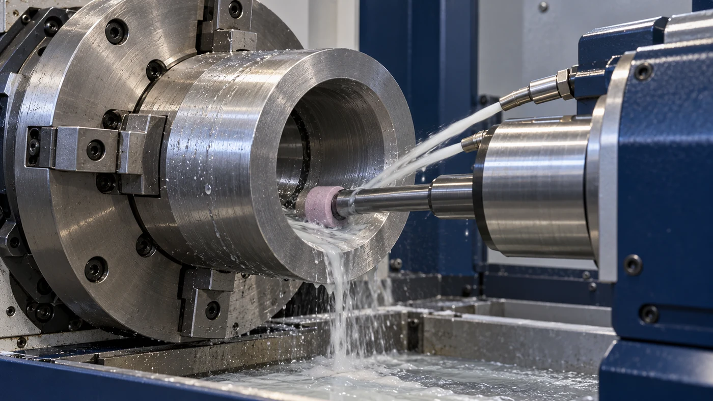
Watch: ID Grinding Coolants & Oils for Precision Bores and Internal Surfaces
Define the Bore and Internal Feature
Internal cylindrical grinding, or ID grinding, uses an abrasive wheel inside a previously formed hole to finish a bore or another internal feature. It differs from drilling with a cutting edge and from honing with a different abrasive-tool arrangement. Bushings, bearing components and precision sleeves can need carefully controlled internal diameters, forms and finishes. Start with the feature drawing. Record the bore diameter and length, whether it is blind or through, nearby shoulders and the material's condition. Identify stock allowance and the surfaces that must relate to the drawing's datums. The available space must accommodate the wheel, quill, fluid delivery and required motion. Workholding also belongs in this review, especially for a thin ring or a long part. QA has coolant and grinding-oil options for evaluation with the complete internal-grinding process and its acceptance requirements.
Match Quill Reach, Rigidity and Spindle
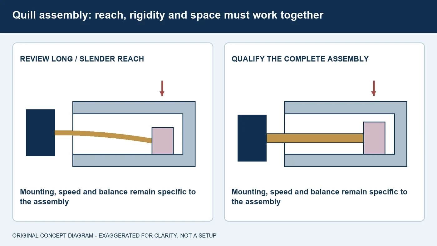
The quill connects the internal grinding wheel to the spindle. Its geometry and mounting can strongly influence the result, so it should not be selected from wheel diameter alone. Review the spindle connection, required reach, quill diameter and material as a coordinated assembly. A longer or less rigid quill can deflect under grinding forces and contribute to poor geometry or chatter. A thicker quill may improve rigidity, but it also changes available space and how far a wheel can be dressed before clearance becomes inadequate. Leave room for the intended coolant-nozzle arrangement near the spindle nose. Use the machine and tooling suppliers' instructions for assembly, balance and permissible speeds. Do not copy a reach ratio or quill material recommendation without checking this application. Establish the mechanical arrangement before comparing fluids; added coolant pressure cannot compensate for an unsuitable wheel and quill assembly.
Review Wheel Size, Contact and Wear
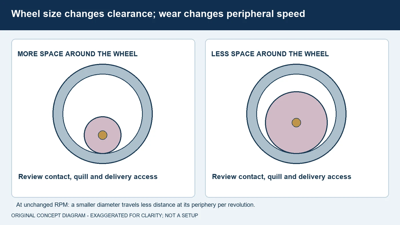
An internal wheel must fit the bore and still leave the required access and clearance. Its diameter and width influence the working contact, the space available for fluid and swarf, and the supported cycle. There is no single wheel-to-bore ratio that should be applied to every ID job. Review the abrasive, grit, grade, bond and structure with the wheel supplier for the material, hardness and required result. Wheel wear matters too. At the same rotational speed, a smaller wheel has a lower peripheral speed because its circumference is smaller. Some systems compensate within an approved process, but that is not a reason to increase spindle speed without verifying every applicable limit. Confirm the minimum usable wheel size, quill clearance and dressing allowance for the assembly. Record wheel condition through the trial so a change caused by wear is not mistaken for a change in fluid performance.
Get Fluid into the Bore and Swarf Out
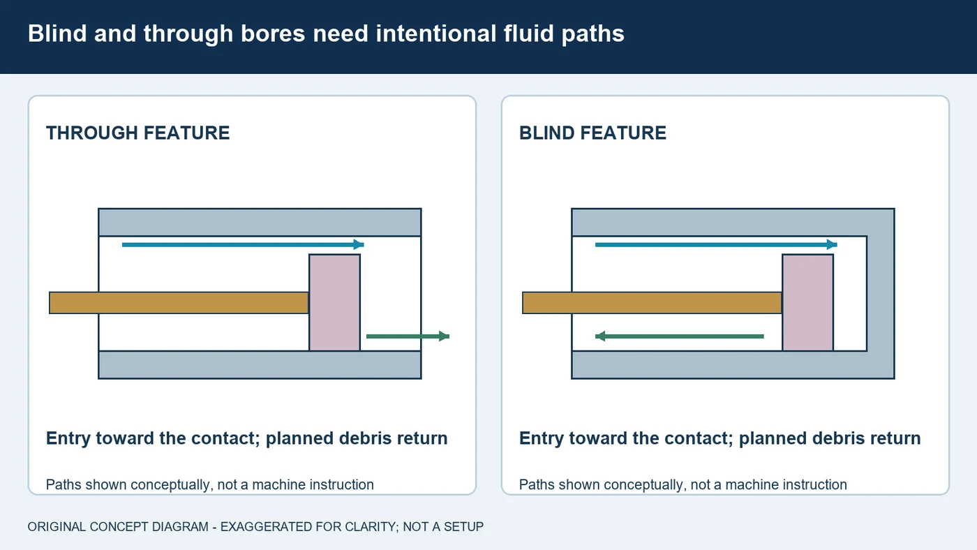
Fluid delivery becomes more difficult when the grinding contact is enclosed by the bore. The wheel and quill occupy space, and the internal contact can leave little clearance for a useful stream or for swarf to escape. A wet bore mouth does not prove that the contact at depth has adequate supply. Examine the entry direction, nozzle access, available flow and the return route during the actual cycle. A blind feature needs particular attention because fluid and debris cannot simply leave through an open far end. Work with the machine and abrasive suppliers on a supported delivery and motion arrangement. Do not add a retraction or raise pressure arbitrarily. Confirm that shoulders, fixtures and changing wheel position do not interrupt the intended path. Record what reaches the contact and how debris returns to the filtration system, rather than judging effectiveness from visible splash outside the part.
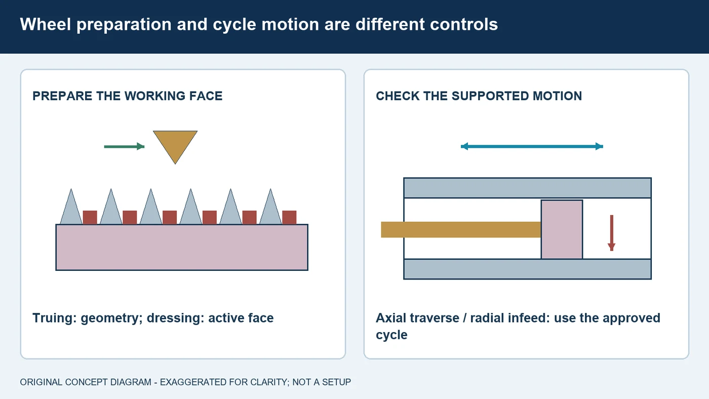
Coordinate Dressing and the Grinding Cycle
A loaded internal wheel can lose cutting ability as swarf accumulates among the abrasive grains. Dressing restores the active face and chip space, while truing addresses the working geometry and relevant runout. Match the tool and method to the wheel's abrasive and bond; conventional and superabrasive systems do not all use the same procedure. The grinding motion also matters. Traverse grinding uses relative movement along the bore, while plunge grinding works at a selected axial location and can form a profile. Machine-approved cycles may include oscillation or a defined finishing stage. Review those motions with the contact and fluid access, rather than copying the cycle from another bore. A very fine dressing condition can change finish while closing the face and increasing thermal or force concerns. Record dresser condition, wheel preparation and the supported cycle before a fluid comparison so their separate effects remain visible.
Select and Maintain the Actual Formulation
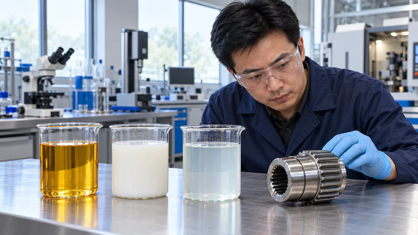
Choose the actual grinding formulation with the machine, wheel, material and downstream requirements. Water-miscible coolants and grinding oils are application-dependent options, not universal substitutes. Evaluate lubrication, heat removal, corrosion protection, foaming behavior and compatibility with the equipment and wheel bond. Include cleaning and residue retention inside the bore. Aluminum and copper alloys need specific staining checks. Cobalt-bonded carbide requires verification of binder compatibility with the selected formulation and grinding arrangement. For water-miscible products, follow the supplied water-quality, mixing and concentration instructions; a refractometer reading may need a product-specific factor. Remove metal and abrasive particles before the fluid returns to the contact, using filtration suited to the process. Follow the machine's thermal-control requirements as well. QA has coolant and grinding-oil options and can help evaluate the formulation, with fluid condition and accepted-part measurements recorded during the trial.
Inspect Taper, Bellmouth and Internal Finish
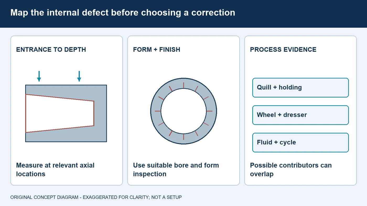
Bore defects can develop differently at the entrance and deeper inside the feature. Record where size changes, bellmouth, taper, chatter or scratches appear, and how the pattern changes through the run. Quill deflection and vibration can influence internal geometry, while loading and poor fluid access can contribute to finish or thermal concerns. These are possible contributors, not a diagnosis from appearance alone. Review the holding arrangement, quill, wheel and dresser, actual supply and cycle with the relevant suppliers. Agree on inspection that can resolve the drawing's requirements. A few diameter readings do not establish every roundness or cylindricity requirement, and an attractive bore surface is not a complete acceptance test. Include the specified surface-integrity checks where required. Make supported process changes in a controlled way, then verify the result at the relevant depths and under consistent inspection conditions.
Bring QA the Complete ID-Grinding Job
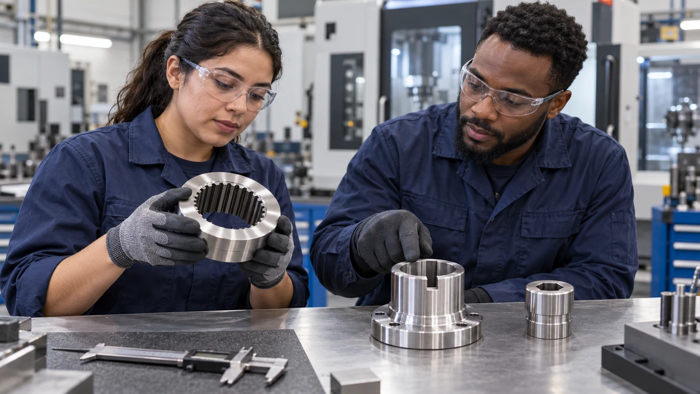
For an internal-grinding review, send QA the bore drawing, diameter, length, blind or through arrangement, material grade and hardness. Include the stock allowance, shoulders, required size, form and finish, and the workholding. Describe the spindle, wheel and quill assembly, dressing method and supported traverse or plunge cycle. Provide the current fluid and its condition, nozzle arrangement, supply, filtration and temperature-control information. Explain what needs to improve using measurements and observations: bellmouth, taper, chatter, wheel loading, scratches, burn, corrosion or cleaning. Photographs of the setup and inspection records help connect the symptom to the actual operation. QA has coolant and grinding-oil options and can evaluate them against the complete manufacturing route. Agree on supported conditions and acceptance criteria with the relevant suppliers before a trial. Keep the tooling and fluid-condition record with the results so the comparison can be repeated in production.
Fluid selection by material
Use these as evaluation questions, not blanket product approvals.
| Material | What to evaluate | What to confirm |
|---|---|---|
| Carbon and alloy steels | Review actual hardness, internal contact, heat removal and corrosion protection. | Wheel, quill, delivery at depth and required bore form. |
| Hardened bearing and tool steels | Evaluate the wheel-fluid system for the specified finish and surface integrity. | Stock allowance, support, drawing inspection and thermal behavior. |
| Stainless steels | Review alloy-specific loading and formulation compatibility. | Wheel face, swarf removal, delivery and subsequent cleaning. |
| Aluminum and copper alloys | Require formulation-specific non-staining compatibility and abrasive review. | Holding distortion, loading, bore residue and cleaning requirements. |
| Cast iron | Evaluate fine-swarf handling, filtration and corrosion protection. | Material condition, internal delivery and accepted surface result. |
| Cobalt-bonded carbide | Verify binder and wheel-bond compatibility for the selected formulation. | Qualified assembly, filtration, fluid access and supplier instructions. |
Questions about ID grinding fluids
Why is quill selection so important for ID grinding?
The quill must reach the feature while remaining suitable for the spindle, wheel and speed. Rigidity, mounting, balance and space for delivery must be reviewed together. A different fluid does not correct an unsuitable assembly.
What wheel-to-bore ratio should every job use?
There is no universal ratio. Confirm the diameter, width, contact, quill clearance, usable wear range and delivery access with the machine and abrasive suppliers.
How should coolant reach the bottom of a blind bore?
Review the actual contact, nozzle access, supported cycle and return path with the equipment suppliers. Wetness at the mouth alone does not prove supply at depth. No single pressure or added retract cycle fits every case.
Can a worn wheel change the process at the same RPM?
Yes. Reducing wheel diameter reduces peripheral speed at unchanged RPM. Any compensation must remain within the permitted assembly and process limits, including clearance.
Is grinding oil always required for internal grinding?
No. Evaluate the specific formulation with the machine, wheel, material and downstream requirements. QA has coolant and grinding-oil options for review.
What causes bellmouth, taper or chatter in a bore?
Possible contributors include quill rigidity, workholding, wheel/dresser condition, fluid access and the cycle. Map the defect with appropriate measurements and investigate the full arrangement before selecting a correction.
Discuss your application with QA
QA Lubricants has coolant and oil options. Send us the operation, alloy, hardness, tooling, current fluid and the problem you want to solve.
Discuss My ApplicationShop Water Diluted CoolantsShop Straight Cutting OilsTechnical references
- JUNKER: internal cylindrical features and small-wheel spindles
- Okuma: ID grinding quill design, reach and coolant-nozzle space
- STUDER: internal grinding quills and support accessories
- Norton: ID contact, loading, quill rigidity and traverse/plunge methods
- LACH DIAMANT: internal grinding, chip removal and targeted coolant
- SuperAbrasives: bore access, wheel wear and ID application requirements
- Norton: wheel specification factors
- Noritake: truing and dressing by abrasive and bond
- Norton: dressing, finish, coolant and machine interactions
- FUCHS: fluid selection and downstream processing
- Blaser: formulation-specific concentration measurement
- UNITED GRINDING: particle removal and temperature regulation
- Mitutoyo: roundness measurement and diameter-method limitations
- Master Fluid Solutions: carbide-binder and wheel compatibility example
Original educational content and illustrations. Confirm current machine, tool and fluid instructions. Trademarks belong to their respective owners.