
Parting & Grooving Coolants and Cutting Oils for CNC Lathes
Explore cutoff and grooving fluid selection for CNC lathes, including chip control, precision coolant delivery, internal and face grooves, material compatibility and troubleshooting.
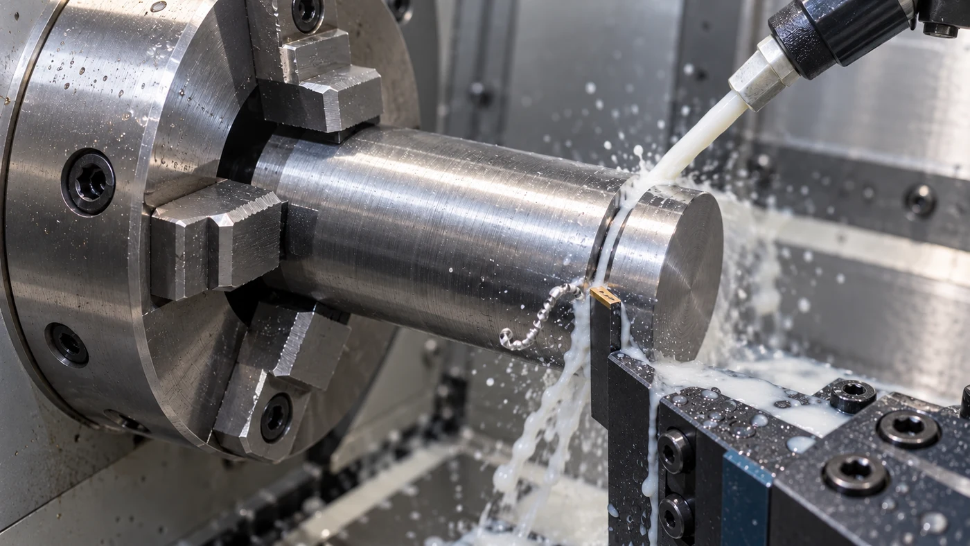
Watch: Parting & Grooving Coolants and Cutting Oils for CNC Lathes
Define the Cutoff or Groove Before Choosing the Fluid
Parting and grooving place a cutting edge in a confined cut, where chip control and fluid access deserve careful attention. In parting, the operation separates a component from bar or tube. A groove leaves a specified recess instead, on the outside diameter, inside a bore or on the face of a part. Start with the drawing and identify the actual operation. Include groove width and depth, corner radii, dimensional tolerance, surface requirement and permitted burr. For cutoff, describe the solid or hollow stock and the approved way the finished component is supported or collected. Tool access, clamping and the remaining connection change as the cut progresses. That complete application determines the tooling and fluid questions. QA has coolant and cutting-oil options, but a fluid family name alone cannot establish the right choice. The goal is a repeatable accepted feature or cutoff, with the machine and tooling working within their intended limits.
Support the Blade and Verify the Cutting-Edge Position
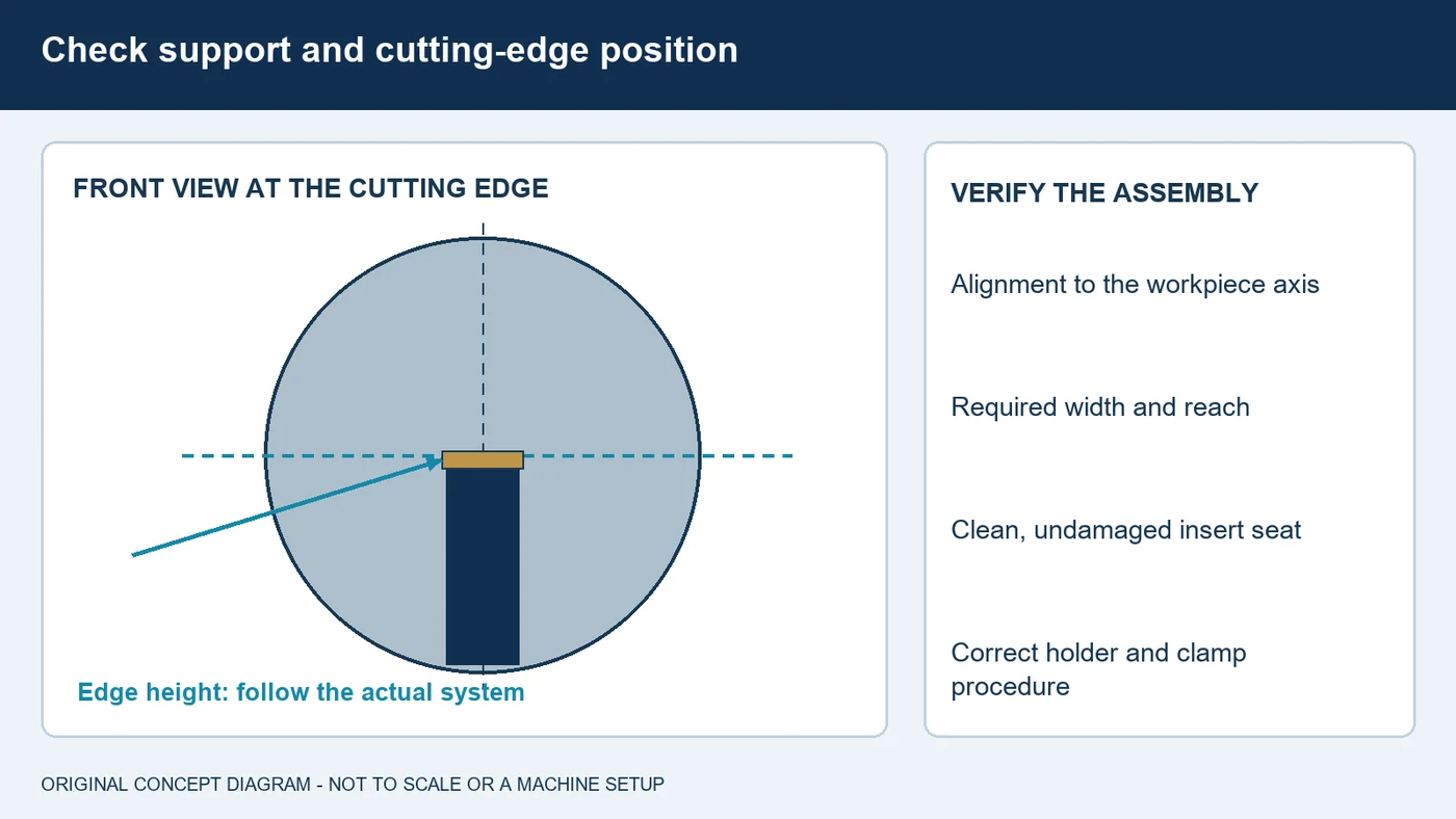
A narrow parting blade works under constraints that differ from a general turning holder. Review its mounting, insert seat and support before comparing fluids. Check cutting-edge position and alignment by the procedure for that exact system. A center-height error changes how the edge cuts, especially as a parting tool approaches the center. Insert width also involves a tradeoff: reducing the removed width can save material and lower force, but the complete tool must retain enough support for the required reach and depth. Use the shortest practical supported assembly that meets the job, following the supplier's limits. Inspect for worn seats, damaged clamps and material trapped at the connection. Do not copy one catalog's numerical overhang or setting limit to every blade design. Record the assembly and measured setup so a mechanical change is not mistaken for a coolant improvement. Make checks and adjustments with the machine stopped through the approved procedure.
Form a Chip That Can Leave the Groove
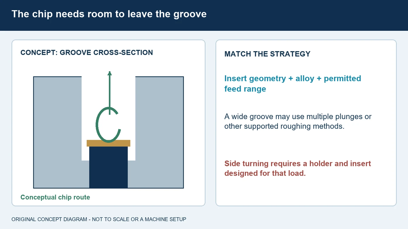
The chip must have a route out of the groove without being trapped between the tool and the freshly cut walls. Dedicated parting geometries can shape a chip narrower than the cut, while other grooving geometries support their own cutting strategies. Choose the insert and operating range for the alloy and operation. Very long chips, rubbing at the walls or repeated packing are reasons to review geometry, feed and delivery together. For a wide external groove, a single full-width plunge is not the only option. Multiple plunges, plunge turning, ramping and a separate finishing sequence may be appropriate when the holder and insert support them. Do not assume that a thin cutoff blade is permitted to turn sideways. Likewise, pecking or small interruptions are process choices with tradeoffs, not a universal chip-breaking fix. Use the tooling supplier's recommended method and record the chip behavior during a fluid trial.
Bring the Fluid to the Edge Inside the Cut
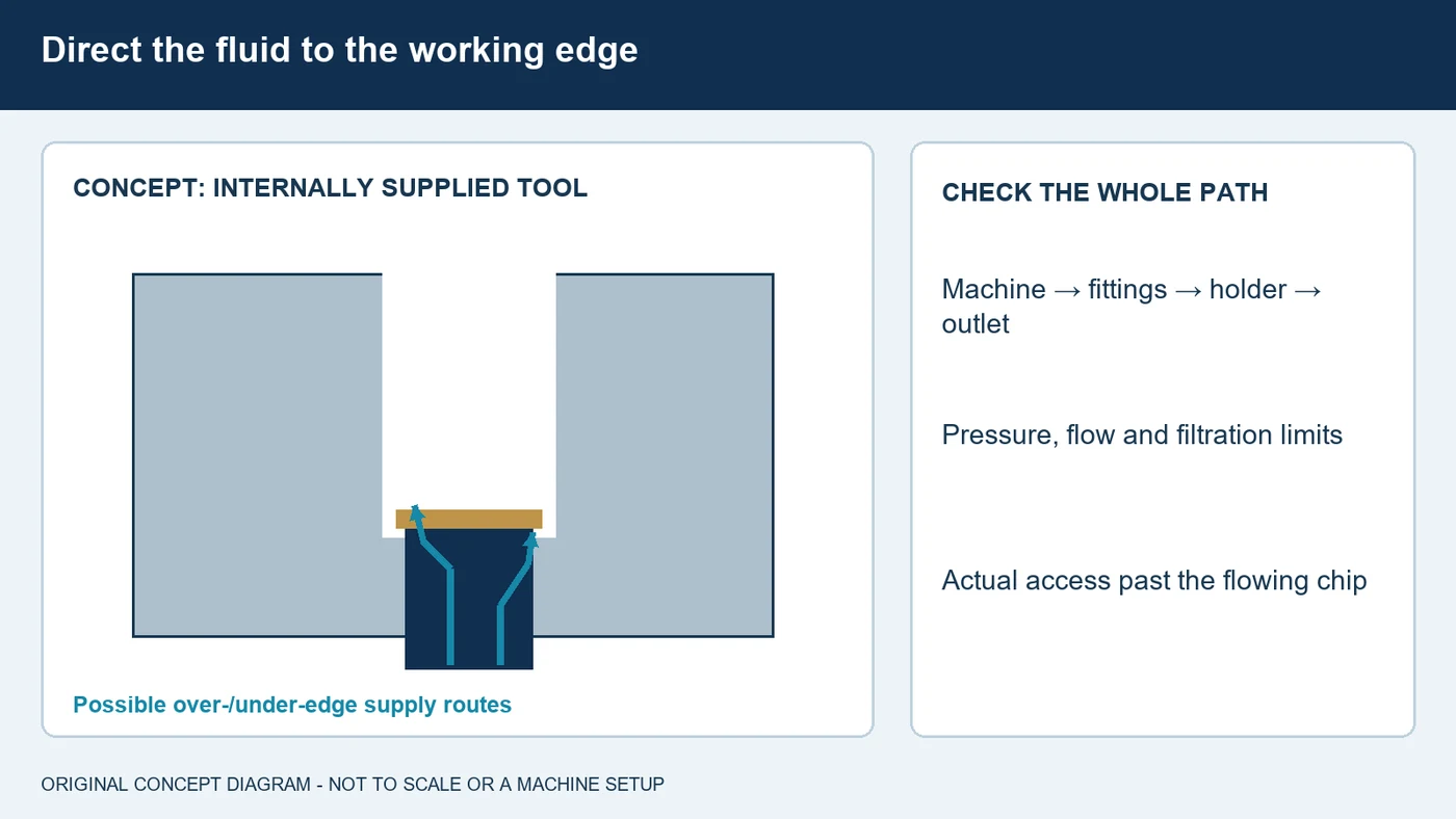
A strong stream outside the part does not prove that useful fluid reaches a cutting edge buried in a deep groove. Workpiece walls and the flowing chip can obstruct external supply. Internally supplied holders, blades or inserts can direct fluid close to the cutting zone when the assembly is designed for that purpose. Some systems supply the rake side, the flank side or both. Their purpose and effect depend on the tool and cut; follow the actual outlet arrangement rather than improvising a connection. Verify the machine, fittings, seals, holder and filtration as a complete rated system. Higher pressure is not automatically the best setting in every material or part of the cut. Use supported pressure and flow guidance, and inspect blocked outlets or chip buildup through the approved maintenance procedure. Keep the delivery setup repeatable when evaluating a formulation. The product and its access to the working edge must be assessed together.
Plan Clearance for Internal and Face Grooves
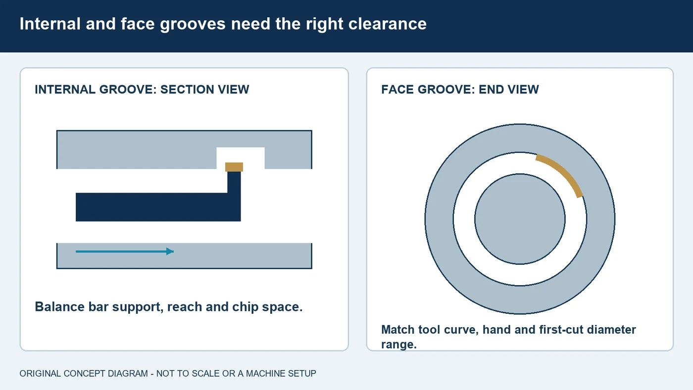
Internal grooving introduces the support and clearance limits of a tool working inside a bore. A larger bar may improve stiffness but leaves less room for chips; a smaller one creates clearance at the expense of support. Choose the assembly, reach and delivery for the bore and groove, then follow the supplier's roughing and finishing strategy. Face grooving is different again. The holder must clear the curved annular feature as it feeds axially into the face. Check the tool's specified first-cut diameter range, hand, curve and depth capability. An external grooving holder should not be substituted without a confirmed application match. Wide or deep grooves may require a planned sequence to preserve chip access before finishing walls and radii. Evaluate the drawing's functional surfaces with the proper inspection method. A successful fluid trial includes those geometry and tool-path requirements, rather than recording tool life alone.
Match the Fluid to the Alloy and Maintain Its Condition
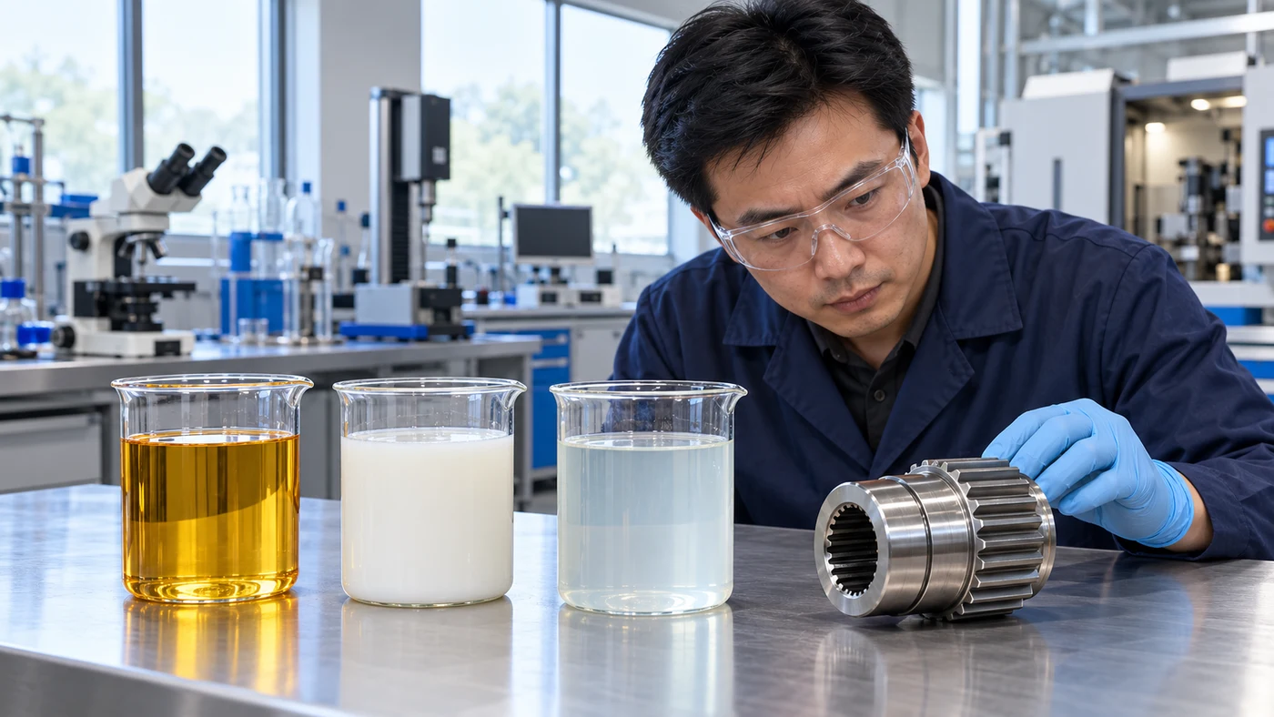
Material grade and condition affect chip formation, adhesion and the load placed on the edge. Stainless steels, titanium and nickel alloys require particular attention to tooling and fluid access, but they should not be assigned one universal cutting recipe. Aluminum alloys also vary; include the alloy's silicon content and the surface requirement in the discussion. For aluminum and copper-containing materials, confirm staining behavior and additive compatibility, including active-sulfur restrictions where relevant. Compare actual water-miscible or straight-oil formulations permitted by the machine and process. Maintain a diluted coolant at its own application recommendation using the prescribed measurement method and refractometer factor. Keep water quality and contamination under review. For a straight oil, follow its own condition and housekeeping instructions. Include every metal sharing the sump and any cleaning, coating or customer-process limits. These details make the selection specific to the part instead of relying on a broad coolant category.
Distinguish Burrs, Chip Jams, Chatter and Edge Damage
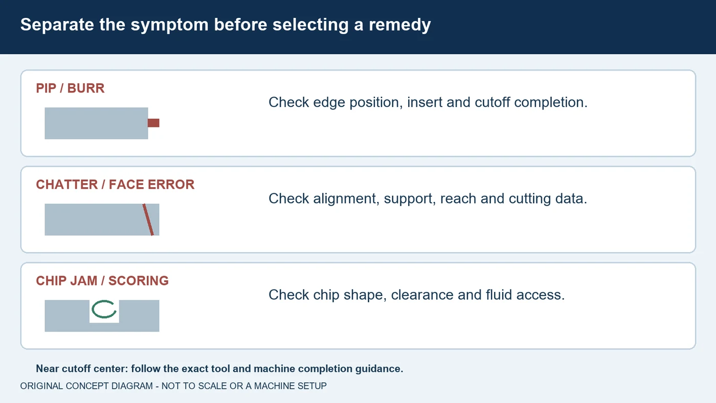
Describe the problem before choosing the remedy. A remaining pip or burr at cutoff completion calls for a review of insert geometry, cutting-edge position, support and the completion strategy. Chatter or a tapered face brings stability, alignment and the cutting recommendation into focus. Chip jams and scored groove walls require attention to chip shape, clearance and actual fluid access. Inspect the insert as well: material buildup, chipping and progressive wear are different observations. During solid-stock parting, the local cutting speed changes with diameter, and the machine's speed limit influences the final approach. Follow the exact tool and machine guidance for that phase, including any feed or coolant changes; do not apply a blanket instruction to every setup. Use a documented next check and measure the drawing requirements consistently. More coolant pressure or concentration cannot replace a correctly assembled, supported and applied tool.
Bring QA Your Complete Parting and Grooving Application
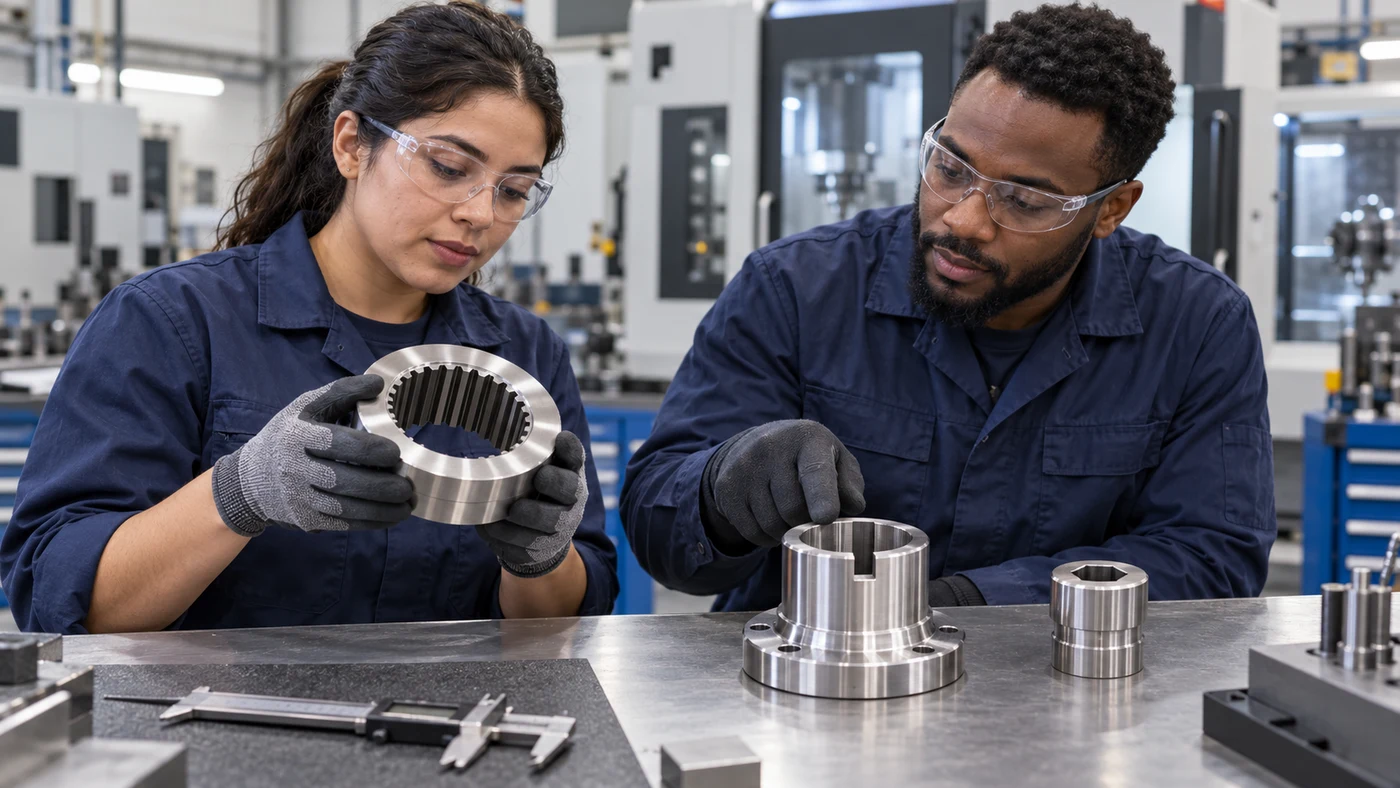
For a parting or grooving fluid inquiry, give QA Lubricants the complete application. Identify cutoff, external grooving, internal grooving or face grooving, and include the finished dimensions, radii and acceptance requirements. Share the exact material grade and condition, the stock diameter or bore, and whether the cut is continuous or interrupted. Tell us the tool system, insert, reach and setup procedure. Describe the machine's available supply, the holder outlets, current product and maintenance practice. Include the problem you want to improve and any staining, cleaning or customer-process restrictions. QA has coolant and cutting-oil options and can help evaluate candidates against that information. Agree on the trial conditions, inspection and acceptable production result before changing the fluid. Explore our machining guides at QA Lube dot com, or call one, eight seven seven, eight seven seven, six two two one.
Fluid selection by material
Use these as evaluation questions, not blanket product approvals.
| Material | What to evaluate | What to confirm |
|---|---|---|
| Carbon and alloy steels | Evaluate chip shape, edge lubrication and actual delivery into the groove. | Grade, hardness, stock condition, insert geometry and permitted operating range. |
| Stainless steels | Review adhesion, heat, work hardening and chip control, including changing conditions near cutoff center. | Exact alloy, blade support, tool supplier's center-approach strategy and machine limits. |
| Aluminum alloys | Evaluate material buildup, surface quality and nonstaining compatibility. | Alloy and silicon content, insert edge/coating, fluid chemistry and downstream appearance requirements. |
| Copper, brass and bronze | Check staining and additive compatibility for the specific alloy. | Active-sulfur restrictions, shared-sump metals, cleaning and final surface requirements. |
| Titanium and nickel alloys | Review cutting-tool suitability, chip control and supported precision delivery. | Alloy and heat treatment, permitted tool grade, pressure/flow limits and customer-process restrictions. |
| Cast iron and hardened materials | Use the wet or dry approach approved for the actual cutting material and assembly. | Hardness, interruptions, tool grade and chip or dust management. |
Questions about parting & grooving fluids
What is the difference between parting and grooving?
Parting separates a component from stock. Grooving produces a controlled recess, which may be external, inside a bore or on a component face. Tool geometry, clearance and completion requirements differ.
Why does coolant struggle to reach a deep cutoff groove?
The workpiece walls and flowing chip can obstruct external fluid access. A compatible internally supplied tool can direct fluid nearer the cutting edge, but the whole supply path, pressure, flow and filtration must suit the assembly.
Is higher coolant pressure always better for parting?
No. Review the material, tool, machine and operating conditions. Tooling guidance includes exceptions, so do not exceed system ratings or treat maximum pressure as a universal setting.
Can the same holder make external, internal and face grooves?
Do not assume so. Internal grooves need bore clearance and support; face grooves require a tool with the correct curvature, hand and first-cut diameter range. Use the holder's specific application limits.
Will changing coolant eliminate the pip left by cutoff?
Pip and burr formation also depend on tool setting, insert geometry, support and the completion strategy. Check those with the tooling supplier before assigning the cause to the fluid.
What should QA know before recommending a parting fluid?
Provide the operation, exact material, stock and groove dimensions, tool assembly, delivery capability, current fluid and acceptance requirements. QA has coolant and cutting-oil options; a product match follows application review.
Discuss your application with QA
QA Lubricants has coolant and oil options. Send us the operation, alloy, hardness, tooling, current fluid and the problem you want to solve.
Discuss My ApplicationShop Water Diluted CoolantsShop Straight Cutting OilsTechnical references
- Sandvik Coromant: parting-off application guide
- Walter: parting-off application information and setup
- Sandvik Coromant: chip control in parting and grooving
- Sandvik Coromant: coolant application and pressure considerations
- ARNO USA: through-tool parting and grooving delivery systems
- Sandvik Coromant: external groove strategies
- Sandvik Coromant: internal grooving clearance and support
- Sandvik Coromant: face-grooving tool selection
- Sandvik Coromant: material-specific parting and grooving
- Sandvik Coromant: parting and grooving troubleshooting
- Blaser Swisslube: product-specific coolant concentration measurement
Original educational content and illustrations. Confirm current machine, tool and fluid instructions. Trademarks belong to their respective owners.