
Plunge Grinding Coolants and Grinding Oils
Explore plunge and radial infeed grinding fluids, working width, wheel preparation, spark-out, journal cooling and inspection for precision metal parts.
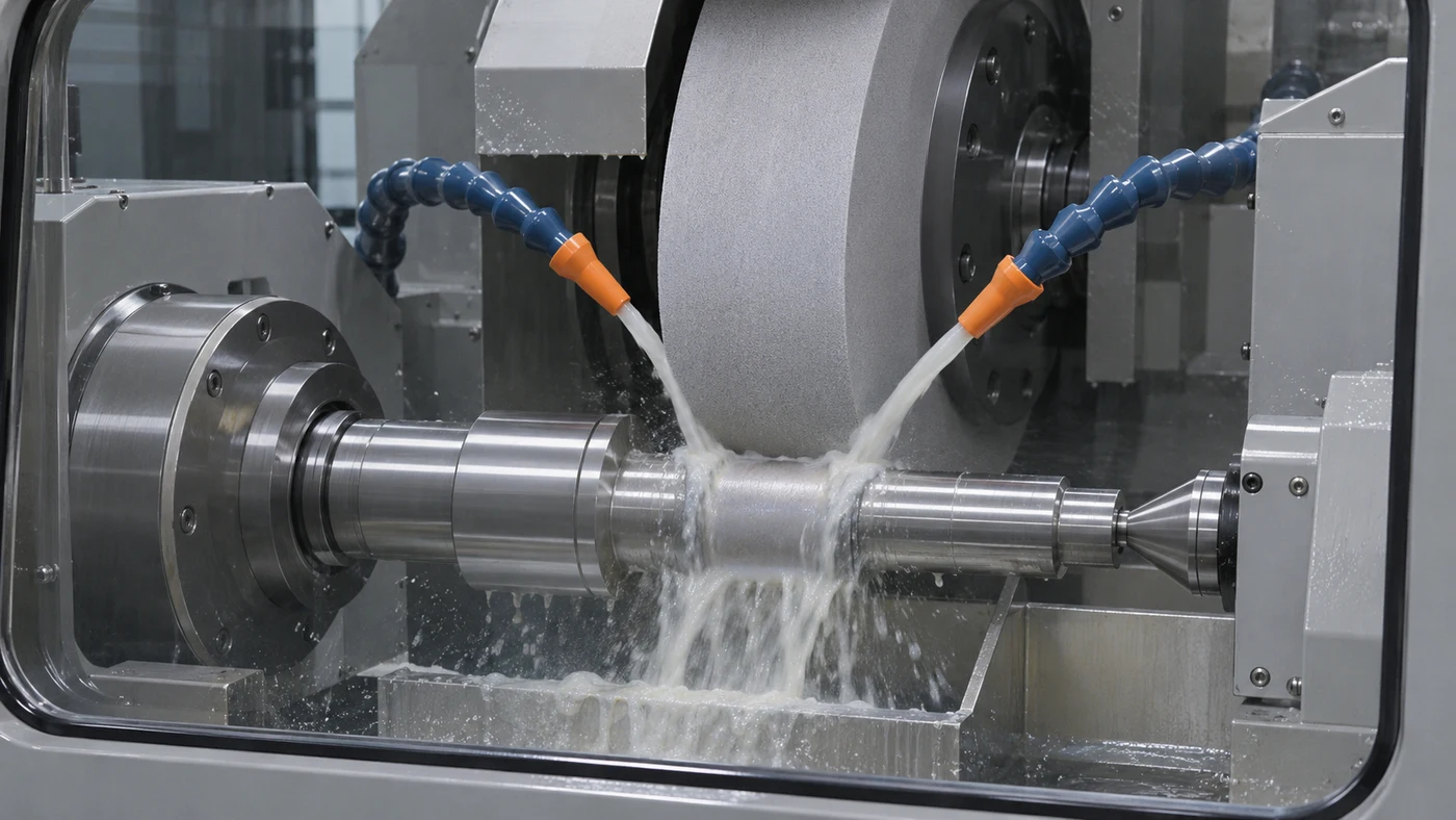
Watch: Plunge Grinding Coolants and Grinding Oils
Plunge Grinding: Radial Infeed at a Defined Feature
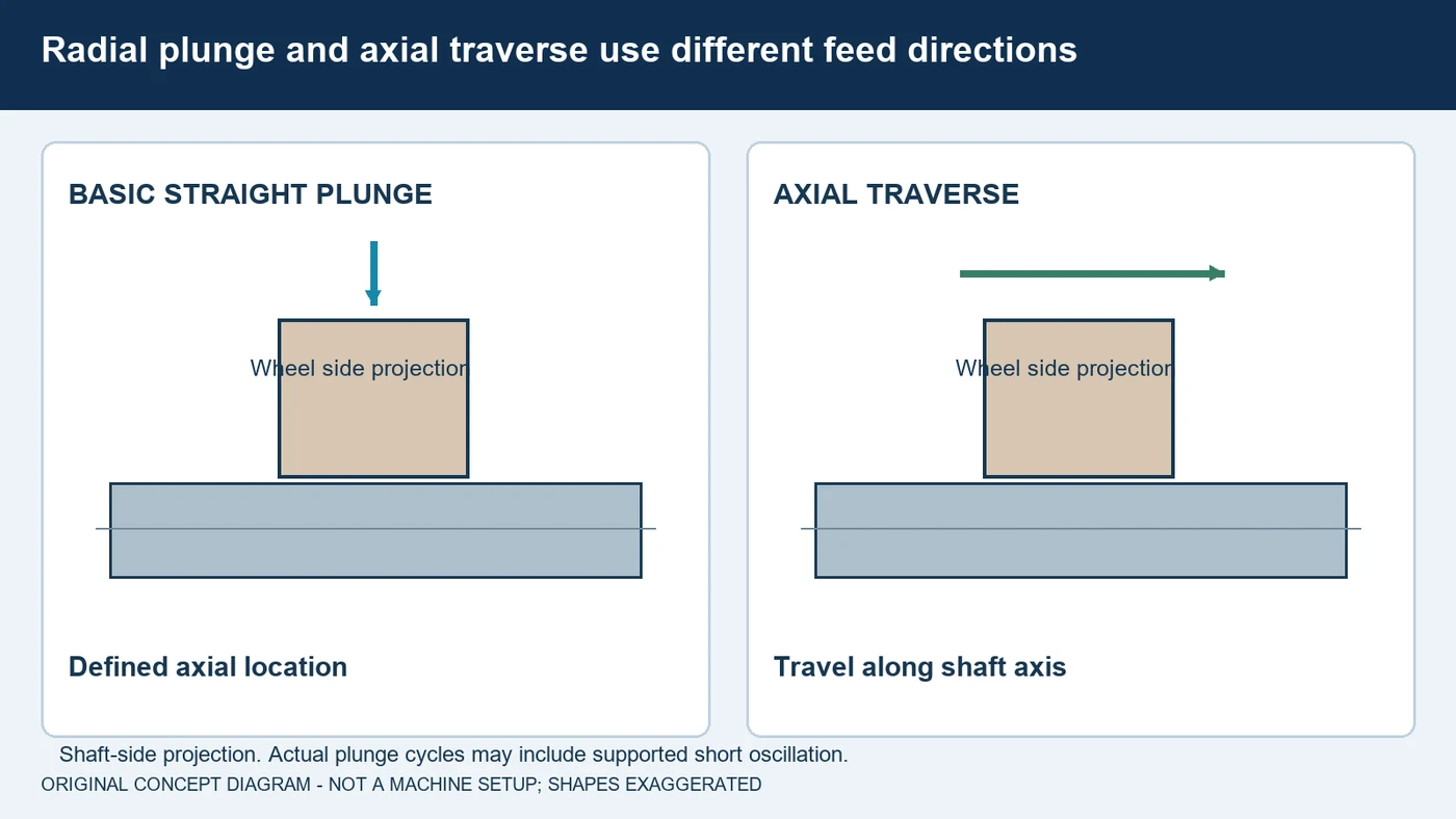
In external cylindrical plunge grinding, the wheel feeds radially into a rotating workpiece to grind a defined feature. In a basic straight plunge, the working width remains at that axial location instead of traversing along the shaft. Bearing seats, journals and suitable formed features are common applications. Some supported cycles include a short oscillation, and angle-plunge or internal operations use different contact arrangements. Identify the actual configuration rather than transferring one cycle between them. Begin with the material, hardness, stock allowance and drawing requirements. Diameter, roundness, cylindricity, shoulder location and surface finish are different acceptance questions. QA has coolant and grinding-oil options for evaluation with the actual machine and abrasive system. This guide emphasizes controlled infeed, useful fluid delivery and evidence from accepted parts.
Review the Working Width and Part Support
The wheel's active width and the feature shape affect how much work is engaged at one time. A broad straight journal, a narrow seat and a shoulder profile do not impose the same contact. Review the actual working width, wheel form, stock allowance and permitted machine capability together. Include how the work is held and driven. Slender parts and changing support conditions deserve a stiffness review with the equipment supplier; do not treat the programmed slide position as a direct measurement of the finished part. Check clearances and support near the feature before evaluating a new fluid. If the process also grinds a face or shoulder, confirm the supported wheel and approach for that contact. An external straight-plunge example is not permission to grind on an unqualified wheel face.
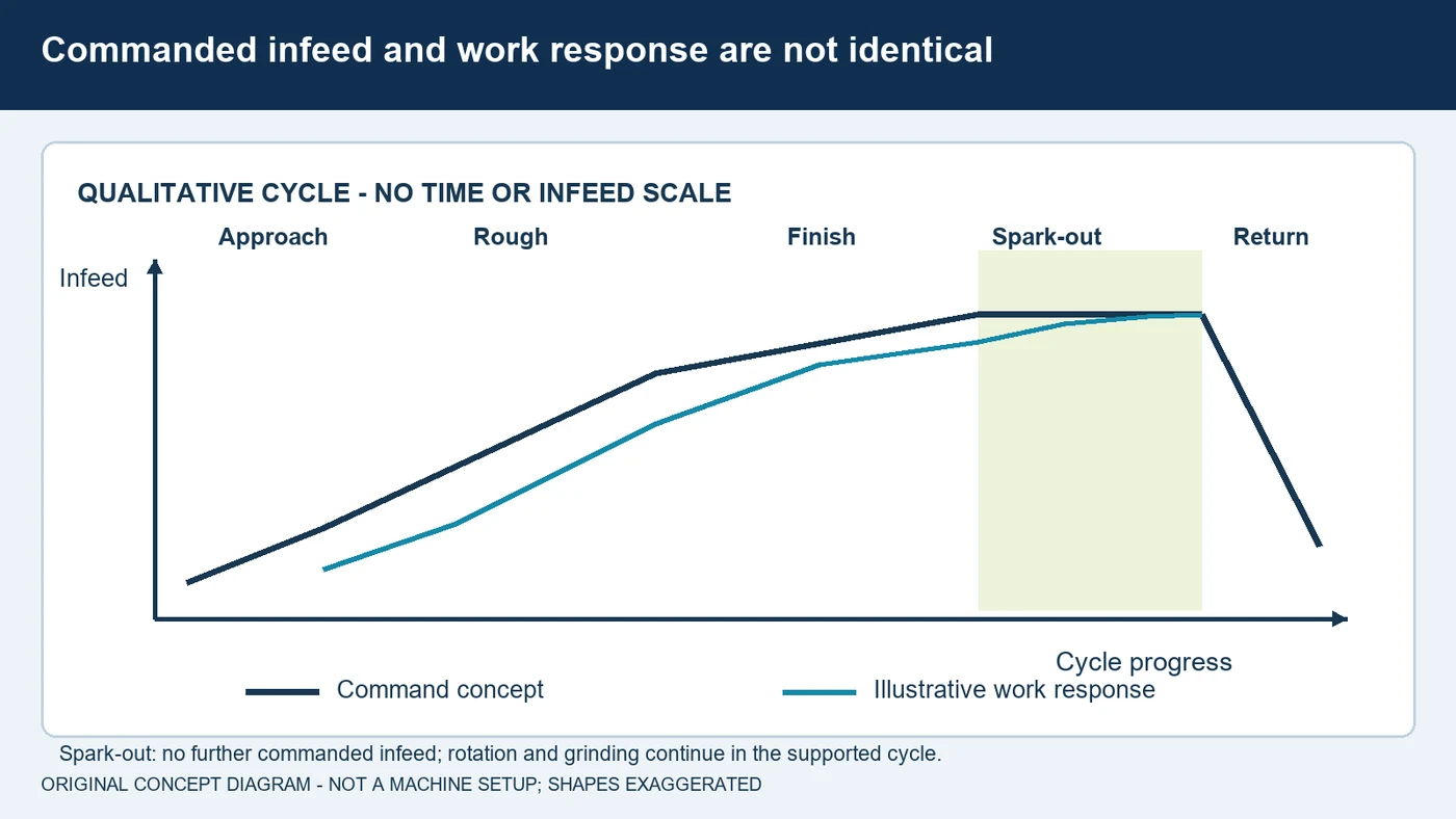
Understand Infeed, Finishing and Spark-Out
A supported plunge cycle may include approach, rough grinding, a finishing stage, spark-out and retraction. During grinding, elastic deflection and wheel wear can make the work's size response differ from the commanded infeed. Spark-out provides a period with no further commanded infeed while the rotating system continues grinding as that response settles. It is not the same as stopping the work or proving that heat damage is absent. The required stages and duration depend on the machine, part, wheel and acceptance requirements. Use the supported cycle and any qualified gauging or feedback system. Do not shorten a dwell or change the infeed based on appearance alone. Compare measured size, form and finish under consistent conditions before accepting a faster cycle.
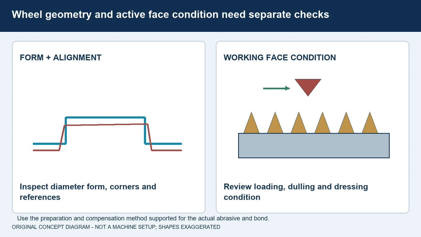
Keep Wheel Form and Face Condition in Control
Plunge grinding uses the working face at a defined location, so its condition and form belong in the process record. Truing concerns geometry and alignment; dressing concerns the active face condition. A wheel can lose a corner or profile, load with material or become dull, and those changes need different checks. Select the complete wheel specification and conditioning tool with the abrasive supplier. Conventional, vitrified superabrasive, resin-bonded and plated systems do not share one preparation method. Record the dressing interval, dresser condition and supported size compensation. When investigating form or finish changes, compare parts at similar points in that interval. A coolant change should not be credited for an improvement actually caused by renewed wheel preparation, or expected to restore a worn profile.
Supply the Entire Active Contact
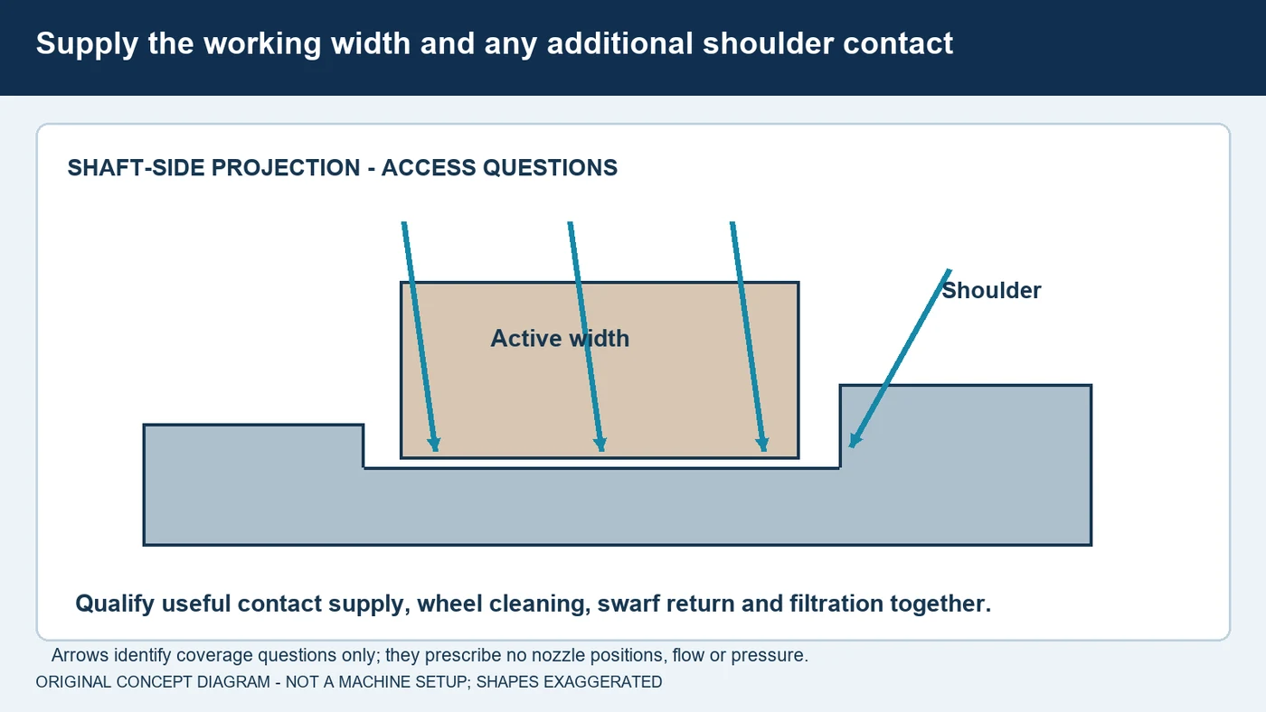
Coolant must reach the active contact across the working width. A stream wetting the middle of a journal does not demonstrate adequate supply near a shoulder or at the edges of a profiled wheel. Review the actual grinding configuration, wheel diameter and supported nozzle arrangement throughout the cycle. Coordinate any separate wheel-cleaning or flushing duties with contact cooling rather than judging effectiveness by visible splash. A restricted internal feature presents different access and return conditions from an open external journal. Keep swarf from returning to the contact through contaminated fluid or inadequate filtration. Document the delivered conditions when comparing formulations. No single pump pressure or flow figure establishes useful supply for every plunge application; qualify the complete arrangement with the machine and nozzle suppliers.
Select and Maintain the Actual Formulation
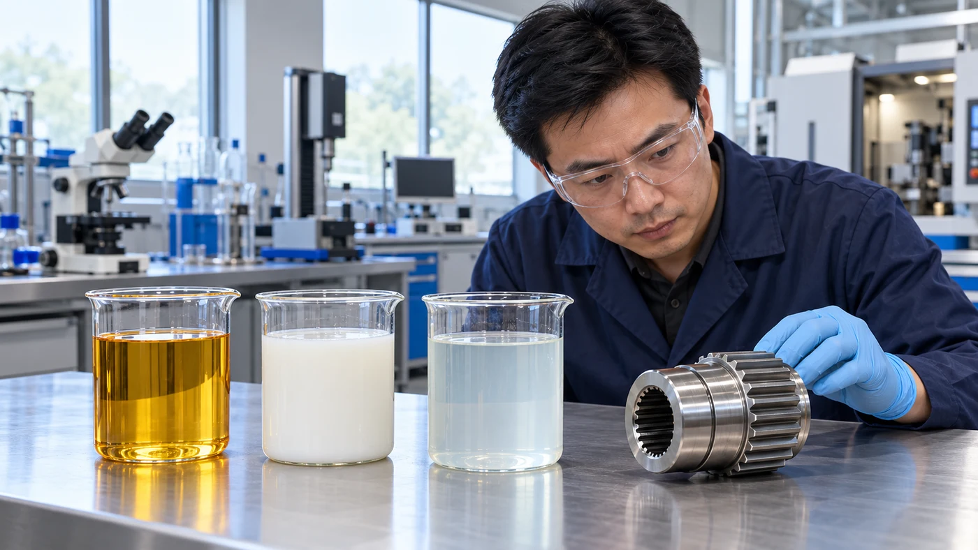
Begin with the fluid types permitted by the machine manufacturer, then review the actual alloy, hardness and abrasive-bond system. Evaluate lubrication, cooling, foam, corrosion protection, residue and subsequent cleaning requirements. Water-miscible coolants and grinding oils can have appropriate applications, but their broad category names do not establish suitability for every journal or profile. Confirm staining compatibility for aluminum and copper alloys. Explicitly review binder compatibility when grinding cobalt-bonded carbide. For diluted products, follow the specified mixing and water-quality instructions, apply the required refractometer factor and record the actual concentration. Maintain the specified fluid-temperature conditions and remove metal and abrasive debris before recirculation. QA has coolant and grinding-oil options for evaluation. A formulation trial should preserve the supported mechanical setup and provide a maintenance record alongside part measurements.
Measure Size, Form and Material Condition
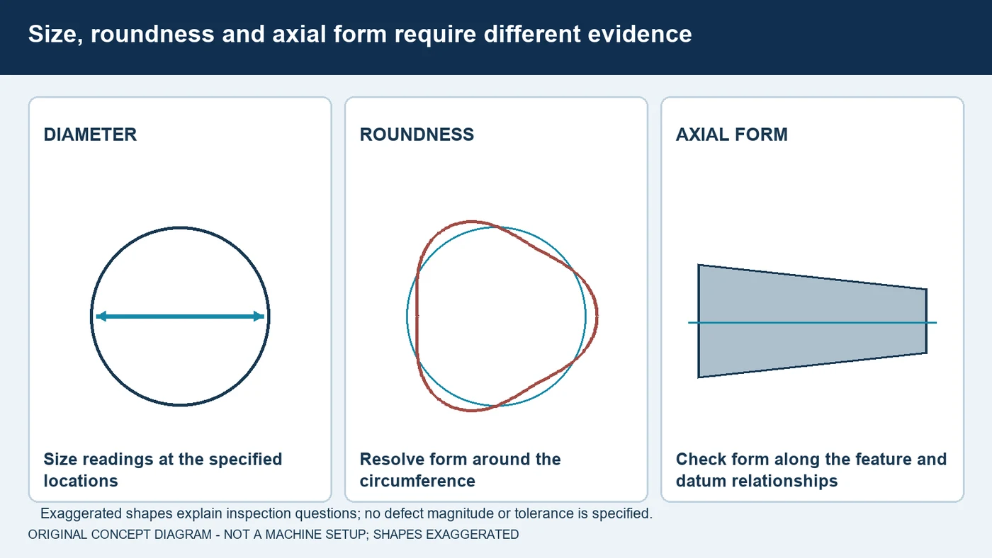
A few diameter readings do not establish complete roundness or cylindricity. Use an inspection plan capable of resolving the drawing's size, form and position requirements. Check the relevant axial locations, shoulder relationship and corner features as specified. Keep measurement support and temperature conditions consistent. Surface texture and material condition are separate questions: a smooth, bright journal is not proof that the part is free of thermal damage. When required, use the qualified surface-integrity method appropriate to the alloy and component specification. If there is taper, waviness, chatter, scratching or size drift, investigate the complete system. Work support, wheel preparation, alignment, stock, infeed, fluid delivery and cleanliness can all be relevant. Make a documented change and repeat the required acceptance checks before adopting the revised process.
Build a Measured Plunge-Grinding Fluid Trial
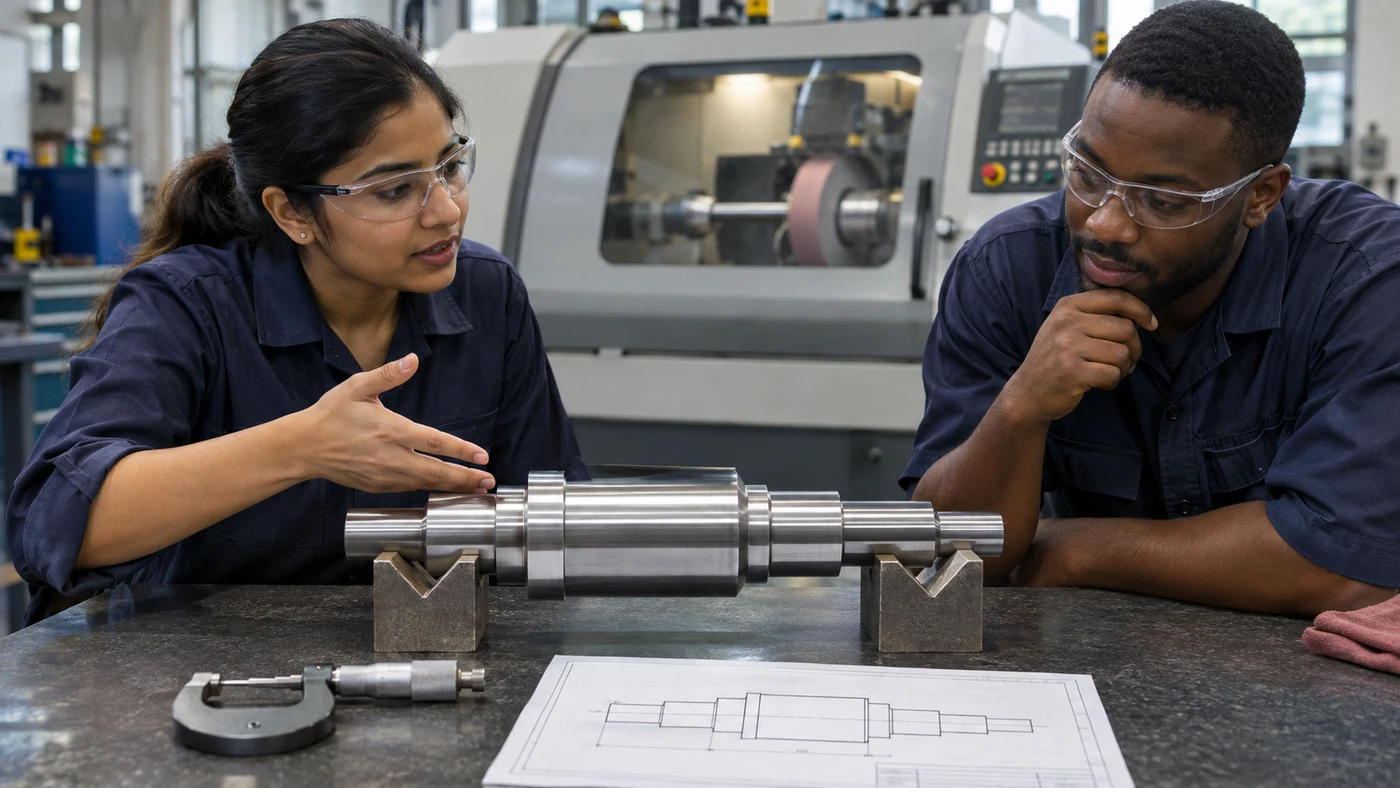
For a plunge-grinding inquiry, send QA the drawing, material and hardness, stock allowance, feature width and required size, form, finish and material condition. State whether the process is external, internal, straight, angle-plunge or a supported oscillating cycle. Describe workholding and support, the wheel specification, dresser, preparation interval and the current cycle. Provide the fluid, delivered supply, return and filtration arrangement, plus temperature information. For diluted coolant, add water-quality and concentration records. Explain the issue using measurements and when it appears relative to dressing or startup. QA has coolant and oil options for evaluation. Define the controlled trial conditions and compare accepted parts, wheel condition, dressing and fluid maintenance together. Confirm the final formulation and operating instructions with the relevant equipment, abrasive and fluid suppliers.
Fluid selection by material
Use these as evaluation questions, not blanket product approvals.
| Material | What to evaluate | What to confirm |
|---|---|---|
| Hardened and tool steels | Review the actual hardness, working width, lubrication and thermal requirements. | Wheel preparation, cycle, support and qualified surface-integrity inspection. |
| Stainless steels and nickel alloys | Evaluate loading behavior, alloy-specific compatibility and contact demand. | Fluid access, wheel bond, work support, finish and downstream cleaning. |
| Cast iron | Review fine-swarf control, cleanliness and corrosion protection. | Supported wheel, filtration, stock condition and accepted size and form. |
| Aluminum and copper alloys | Check staining compatibility and material loading in the qualified process. | Abrasive selection, fixture stiffness, residue removal and drawing requirements. |
| Cobalt-bonded carbide | Explicitly verify binder and abrasive-bond compatibility. | Actual formulation, supported preparation method, cleanliness and supplier instructions. |
Questions about plunge grinding fluids
How is plunge grinding different from traverse grinding?
A basic external cylindrical plunge feeds radially at a defined axial location. Traverse grinding moves along the work axis. Some supported plunge cycles include a short oscillation; identify the actual machine cycle.
Does spark-out mean the part stops rotating?
No. In a typical spark-out stage there is no further commanded infeed while the rotating system continues grinding as its response settles. Use the machine-specific cycle.
Is there a standard spark-out time for all parts?
No. Determine the supported cycle from the actual part, stiffness, wheel, process response and accepted size, form and finish. Do not transfer a fixed dwell between different applications.
Can one nozzle setting serve every plunge configuration?
No. Working width, shoulder contact, wheel size and internal access change the delivery problem. Qualify useful supply and the complete return circuit.
Will diameter measurements alone prove cylindricity?
No. Size, roundness, axial form and datum relationships require an inspection plan capable of resolving each specified requirement.
Which QA fluid should I use for plunge grinding?
QA has coolant and grinding-oil options. Provide the material, machine, wheel and bond, support, cycle, delivery and acceptance requirements so the actual formulation can be evaluated.
Discuss your application with QA
QA Lubricants has coolant and oil options. Send us the operation, alloy, hardness, tooling, current fluid and the problem you want to solve.
Discuss My ApplicationShop Water Diluted CoolantsShop Straight Cutting OilsTechnical references
- STUDER: radial plunge and axial traverse cylindrical grinding
- Tyrolit: external cylindrical plunge applications and abrasive systems
- STUDER: supported plunge cycles and spark-out
- NIST: plunge-cycle stages, deflection and measured process feedback
- SCHNEEBERGER: plunge, angle-plunge and oscillation as distinct supported processes
- Norton: wheel truing, dressing and form loss
- STUDER: controlled coolant delivery and nozzle systems
- Norton: finish, delivery, oscillation and machine-condition interactions
- FUCHS: material and downstream requirements for fluid selection
- Blaser Swisslube: concentration measurement and product factors
- UNITED GRINDING: clean fluid and thermal regulation
- UNITED GRINDING: thermal damage and material-appropriate testing
- Master Fluid Solutions: carbide-binder and wheel-bond compatibility example
Original educational content and illustrations. Confirm current machine, tool and fluid instructions. Trademarks belong to their respective owners.