
Shaping, Planing & Slotting Cutting Oils and Coolants
Compare metal shaping, planing and internal-keyway slotting fluids: cutting motion, return relief, blind-slot chip clearance, material compatibility and finish checks.
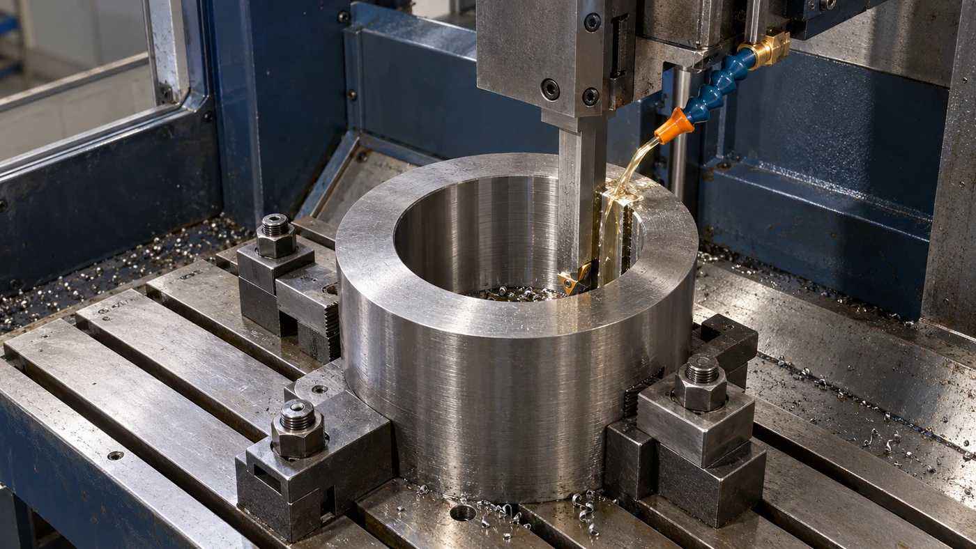
Watch: Shaping, Planing & Slotting Cutting Oils and Coolants
Identify the Reciprocating Cutting Application
Shaping, metal planing and reciprocating slotting remove material through repeated linear cutting strokes. They remain useful for applications such as flat and angled surfaces, grooves and internal keyways when the machine and tooling suit the geometry. This guide covers metal cutting with a single-point or single-edge tool. It does not treat slot milling, woodworking planers or gear shaping as the same operation. Modern shops may also produce internal slots with an inserted tool on a suitable CNC machine; suppliers often describe that process as CNC broaching. Identify the method actually being used before selecting a fluid. Record the feature drawing, alloy, hardness, slot or surface length and required finish. QA has coolant and cutting-oil options, but a suitable choice begins with the application, including tool access, return motion and chip escape, rather than a generic product described simply as slotting oil.
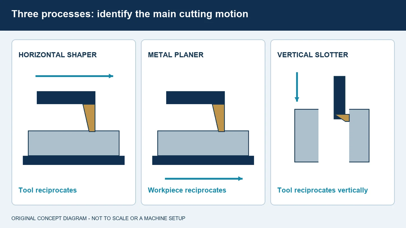
Understand Which Part Moves
A conventional horizontal shaper carries the cutting tool on a reciprocating ram. The workpiece is held on the table, with the appropriate feed between cuts. A traditional metal planer instead moves the clamped workpiece on a reciprocating table beneath the cutting tool, with the required tool feed. A vertical slotter uses vertical reciprocating tool motion to reach features such as internal keyways. These distinctions matter when planning delivery hoses, guards, fixture clearance and the route taken by chips. The return and feed arrangements depend on the machine; a quick-return mechanism is not an instruction to use the same cutting conditions on every model. Confirm the intended cutting direction, stroke position and feed timing from the equipment procedure. Keep the complete travel envelope clear, including the workpiece, fixtures, toolholder and delivery hardware. A fluid nozzle must reach the cut without entering a moving ram or table's path.
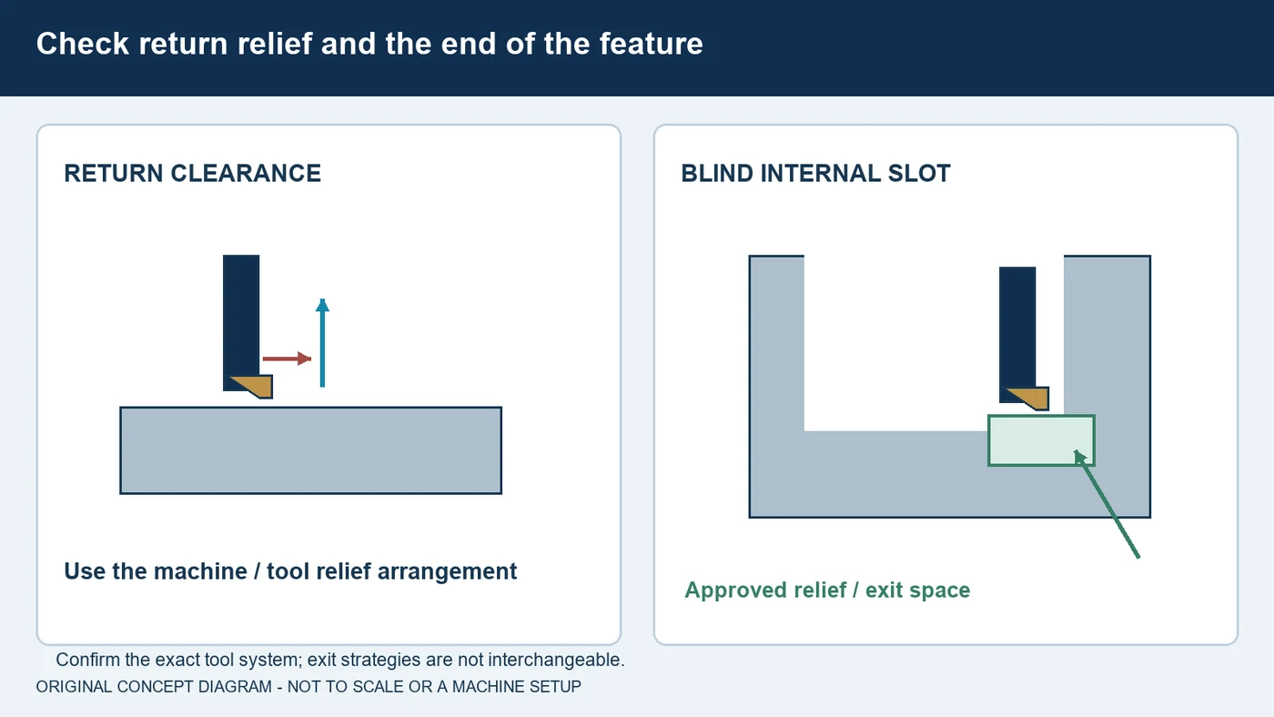
Provide Return Relief and End Clearance
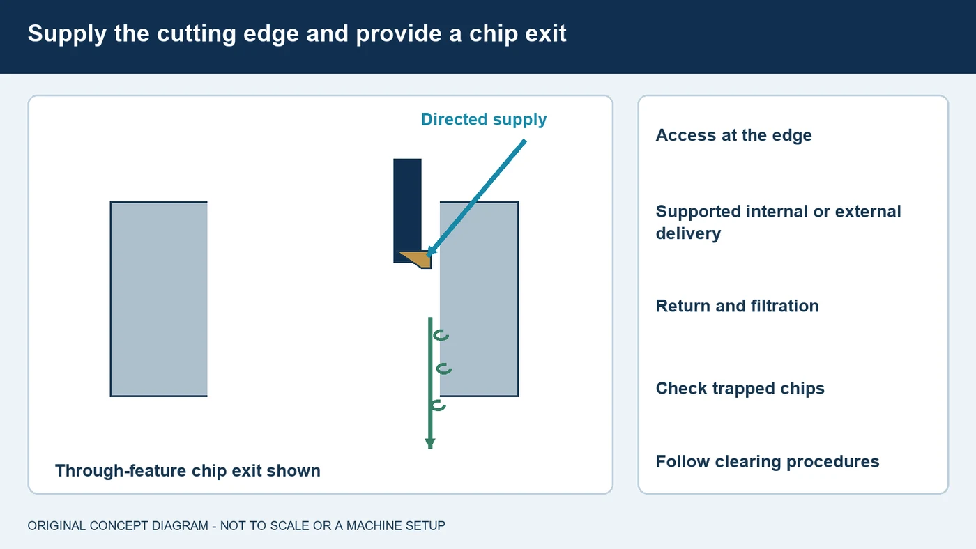
A non-cutting return needs the clearance specified by the machine and tool arrangement. Depending on the system, a clapper or controlled relief motion prevents the tool from dragging across the new surface. Internal slots also need an appropriate end condition. A through feature and a blind keyway create different clearance and chip-removal problems. Tool suppliers show relief grooves, cross-hole openings and other application-specific exit arrangements, but their instructions are not interchangeable. One system may permit a programmed exit that another specifically prohibits. Use the exact tooling guidance and the part designer's approval for any relief feature. Check that the cutting edge, body and retained chip can complete the stroke without bottoming or contacting a shoulder. Fluid cannot compensate for missing mechanical clearance. For a blind feature, evaluate where chips accumulate through repeated strokes and how the approved delivery arrangement removes them before they obstruct the next cut.
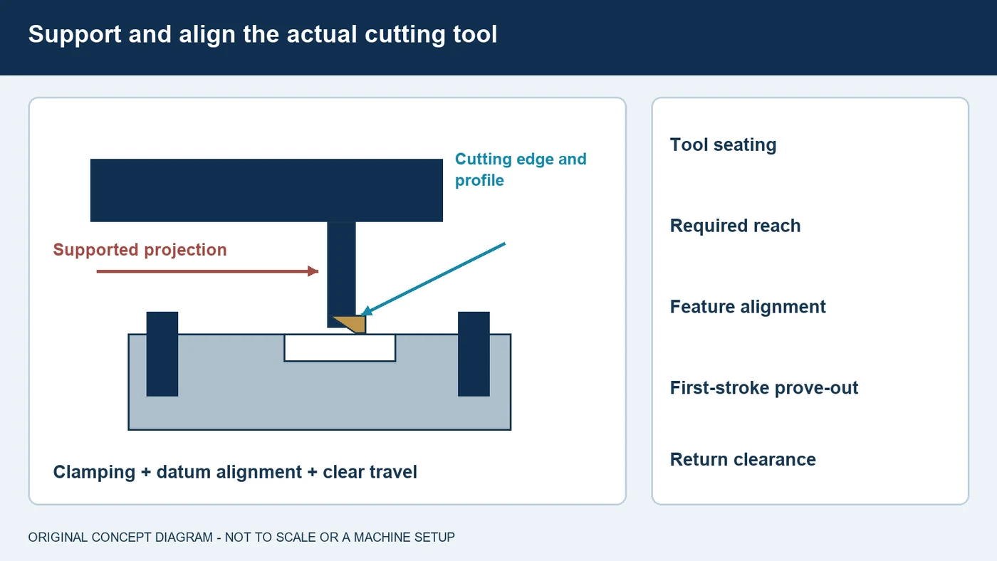
Control Tool Geometry, Overhang and Workholding
Tool width and profile must suit the required feature, with the cutting geometry and substrate selected for the material and method. A narrow internal keyway also limits the tool body's available space. Check the holder, insert seating or sharpened edge, projection and machine interface by the tooling procedure. Use the supported reach needed for the feature rather than assuming a longer bar behaves like a short one. Establish the workpiece datum and clamping arrangement so that the part remains supported throughout the cutting load. Inspect alignment relative to the bore, surface or slot being produced. Follow the machine maker's setup and prove-out procedure, including checks of the first cutting stroke, return and any relief motion. Do not transfer infeed per stroke or linear feed from a different tool system without review. Keep the tool condition and setup consistent when evaluating a fluid change, so mechanical variation does not obscure the result.
Deliver Fluid to the Edge and Remove Chips
Where wet cutting is specified, direct the fluid toward the active edge and the chip-forming region. A stream striking the workpiece above a deep slot may not reach the place that needs lubrication. Some inserted internal-slot tools provide through-tool delivery close to the insert; other arrangements use an external nozzle. Confirm the supported method for the actual tool. Inspect the complete supply and return circuit, including screens and filtration, rather than judging it only by pump pressure. In an internal feature, chips can collect in a relief pocket or other restricted space. Their removal must be part of the established process, with access and an exit route that suit the feature. Do not rely on increasing flow to overcome bottoming or a blocked passage. Follow the equipment's chip-clearing procedure and keep hands and delivery adjustments away from moving strokes. Record chip behavior and edge condition alongside the resulting surface.
Match the Fluid to Material and Machine
These operations do not all require an identical fluid. Published equipment includes wet slotting arrangements and dedicated keyseating systems with dry-machining capability. Use the method qualified for your machine, tool and part. In a wet application, review the actual cutting oil or water-miscible formulation for lubrication, cooling, corrosion protection and material compatibility. Some products list shaping among their uses, but that does not qualify every oil for every slotting tool or material. Aluminum and copper alloys require specific staining and compatibility checks. Consider cleaning, storage and later manufacturing operations as well. Keep machine guide, hydraulic and cutting-fluid requirements distinct unless the equipment explicitly approves a shared product. If a water-miscible formulation is selected, follow its water-quality, mixing and concentration instructions. Apply the product-specific refractometer factor where required. QA can review coolant and cutting-oil options with these requirements, without assuming one viscosity, additive package or concentration fits every application.

Inspect the Feature and Diagnose the Cause
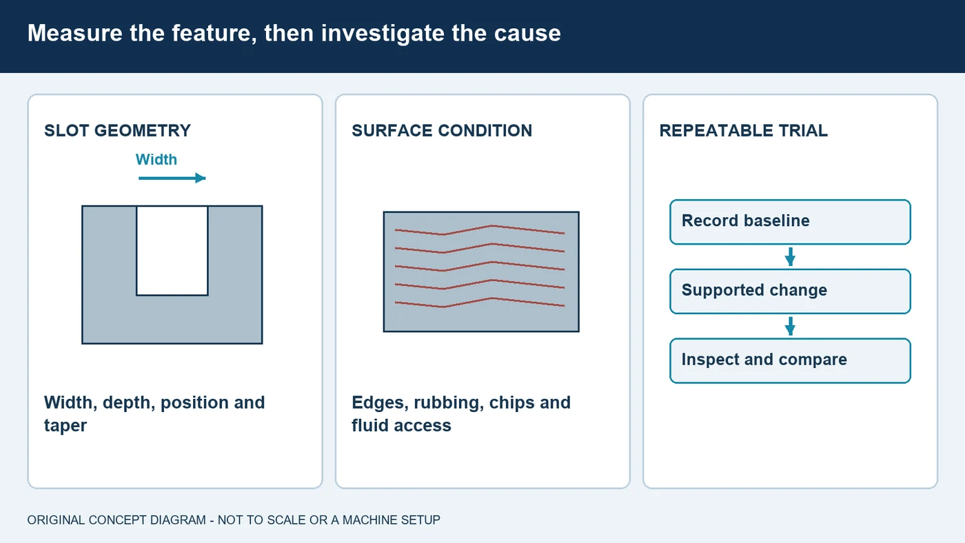
Inspection should reflect the feature being made. For a keyway, establish the required width, depth, length, position and relationship to the bore, together with any corner or relief requirements. For a shaped or planed surface, use the drawing's flatness, angle, dimensional and finish requirements. Do not infer an acceptable fit from surface brightness alone. If a slot changes width or depth along its length, review alignment, tool projection, support, edge condition and the programmed or mechanical motion. A rough surface also calls for examination of the material, chips and fluid reaching the edge. Distinguish rubbing on return from damage during the cutting stroke. Establish a known setup and document the result before changing the formulation or delivery. Compare accepted measurements, surface condition, chip removal and tool wear over a defined trial. A repeatable improvement is more useful than a single part that happens to look better.
Bring QA the Complete Slotting or Planing Job
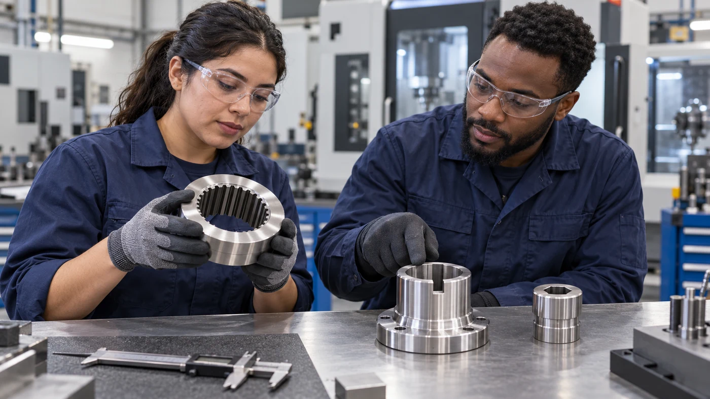
For a shaping, planing or slotting fluid review, send QA the feature drawing, material grade and hardness, and the actual machine and tool system. Include the cutting length, bore or access dimensions, tool width and reach, and whether the slot is open-ended or blind. Describe the return relief and chip-clearance arrangement, the current fluid and its delivery method. Explain what you want to improve, such as finish, dimensional consistency, chip removal, corrosion control or cleaning. Photographs of the setup and cutting edge, together with accepted and rejected measurements, help define the problem. QA has coolant and cutting-oil options and can work with you on an evaluation for the complete manufacturing route. Where tooling or equipment requirements govern the choice, involve those suppliers before changing the method. Agree on the trial conditions and the parts to inspect, then retain the results so the selected approach can be assessed consistently in production.
Fluid selection by material
Use these as evaluation questions, not blanket product approvals.
| Material | What to evaluate | What to confirm |
|---|---|---|
| Carbon and alloy steels | Match lubrication and the cutting edge to the actual hardness and load. | Tool system, infeed, surface requirement and later heat treatment. |
| Stainless steels | Review the specific alloy, edge condition and stable chip removal. | Tool substrate, support, qualified cutting conditions and formulation. |
| Aluminum alloys | Evaluate lubrication, non-staining compatibility and cleaning. | Actual alloy, finish, chip behavior and downstream requirements. |
| Copper and brass alloys | Require product-specific staining and chemistry compatibility checks. | Exact alloy and product compatibility; do not generalize across cutting oils. |
| Cast iron | Use the machine-supported wet or dry method and particulate control. | Iron grade, collection or filtration, housekeeping and corrosion protection. |
| Hardened and specialty metals | Treat as a specifically qualified tool-and-machine application. | Actual hardness, cutting feasibility, tool reach and dimensional requirements. |
Questions about shaping, planing and slotting fluids
What is the difference between shaping and metal planing?
A conventional shaper reciprocates the tool over the workpiece. A traditional metal planer reciprocates the clamped workpiece beneath the tool. The feed and return arrangements depend on the equipment.
Is slotting the same as slot milling?
Not in this guide. Reciprocating slotting uses repeated linear strokes with a single-point or inserted edge. Slot milling uses a rotating cutter and needs its own tooling and fluid guidance.
Can a blind internal keyway be cut without an exit relief?
Confirm the exact tool system and feature design. Blind-slot tools need the specified end clearance and chip space. A fluid stream cannot substitute for missing relief or prevent mechanical bottoming.
Does every slotting machine need cutting oil?
No universal rule applies. Equipment may support wet cutting or a qualified dry process. Confirm the actual machine, tooling and material before selecting a fluid or changing the method.
Can cutting fluid replace the machine's way or hydraulic oil?
Only where the equipment explicitly approves the product for those functions. Otherwise, follow the separate cutting, guide and hydraulic-fluid requirements.
What information does QA need for a slotting-fluid review?
Send the drawing, alloy and hardness, machine and tool details, feature depth and access, return and chip-clearance arrangement, current product and the result you want to improve. QA has coolant and cutting-oil options.
Discuss your application with QA
QA Lubricants has coolant and oil options. Send us the operation, alloy, hardness, tooling, current fluid and the problem you want to solve.
Discuss My ApplicationShop Water Diluted CoolantsShop Straight Cutting OilsTechnical references
- AMCO: horizontal shaper motion and worktable feed
- Zurken: distinction between ram-type shapers and metal planers
- PECO: metal planing machines, return motion and feed arrangements
- CABE: vertical slotting machines and separate guide lubrication
- Leistritz: incremental keyseating and return relief
- HORN: single-edge broaching application and return-clearance guidance
- CNC Broach Tools: blind keyway relief and chip-clearance examples
- HORN: internal coolant supply at the insert and groove
- Premier Form Tools: keyway and narrow-slot tooling applications
- Leistritz: machine-supported dry keyseating configurations
- Martin Gard: cutting-oil product with shaping among its applications
- FUCHS: material compatibility, downstream work and fluid trials
- Blaser: product-specific coolant concentration measurement
- HORN: application data for reciprocating internal-slot cutting
Original educational content and illustrations. Confirm current machine, tool and fluid instructions. Trademarks belong to their respective owners.